IDM Pedals
Effect Pedals for the Electrosmith Daisy
OverviewGlossary
Pedals
IDM PEDALS
Pedals
EQ
Equalization effects are audio processors that work by adjusting different frequency bands in the input signal. These effects range from the subtle and utilitarian (e.g. a tone control which rolls off the treble) to more creative uses of equalization such as wah-wah pedals. When working with analog or time-domain digital signals, equalization is done using filters.
EQ: Lowpass Filter
More Info...
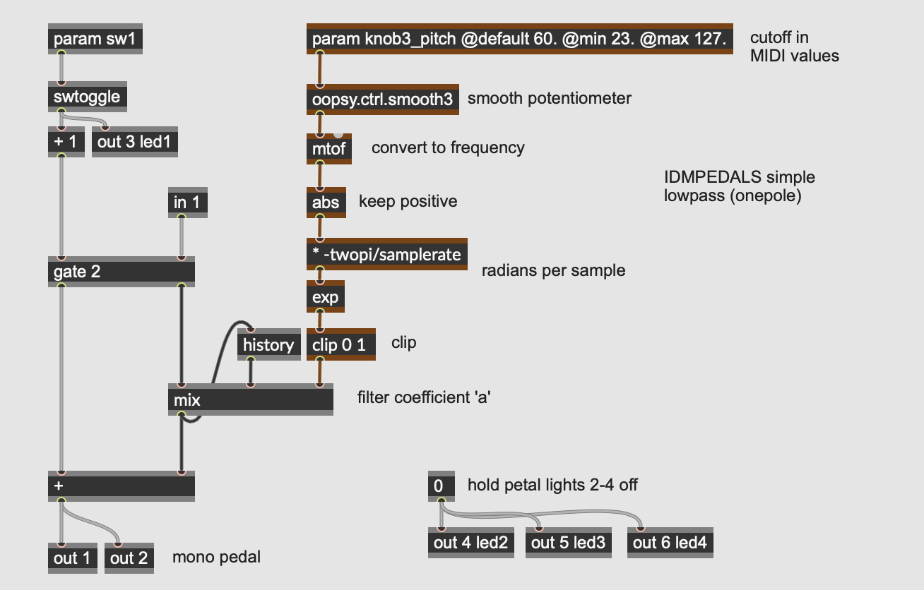
This pedal implements a simple one pole lowpass filter with a single knob (param knob3, at the top-right) controlling the [cutoff frequency]. Time-domain filters are implemented using short delays, so the history and mix operators do the actual filtering of the signal.
The desired cutoff frequency coming from the parameter knob is initially expressed as a MIDI value in the range of 23 to 127 (30 Hz to 12.5 kHz).
Hint: using a MIDI range as a parameter instead of frequency is a simple way to make the knob have a logarithmic frequency (or pitch linear) response; moving the knob by twelve steps, for example, will move the parameter by an octave anywhere in its range.
After being smoothed (using the oopsy.ctrl.smooth3 abstraction) and converted to frequency (using the mtof operator), the cutoff frequency is converted into the a coefficient for a simple first-order IIR lowpass filter:
y[n] = ax[n] + by[n-1]
where...
x = the input signal
y = the output signal
n = time (n is now, n-1 is one sample ago, etc.)
Fc = cutoff frequency
SR = sampling rate
Ω = Fc*2π/SR (sampling increment)
a = e^-Ω
b = 1.0-a
This calculation takes converts our desired cutoff frequency into a single coefficient defining how much smoothing to apply to the input signal by mixing it with the previous output sample from the history operator.
A coefficient of 0.0 will leave the input signal unchanged, which is the equivalent of the filter cutoff frequency being equal to the Nyquist frequency - no filtering at all. By a similar token, a coefficient of 1.0 will make the filter output its previous state as direct current and include no new information - a cutoff frequency of 0 Hz. A coefficient of 0.5 will mix the incoming signal and previous output in equal amounts, resulting in a cutoff frequency of half the frequency range of the system (or a quarter of the sampling rate).
This effect is quite simple and would be an unlikely candidate on its own for an entire effects pedal - it’s much closer to the tone control circuit on an electric guitar or an EQ knob on a consumer stereo system. However, when combined with other algorithms a simple lowpass filter can be used to many creative ways.
EQ: Parametric Equalizer
More Info...
This pedal consists of a three-parameter, single band parametric equalizer. Invented by Burgess Macneal in the mid-1960s, parametric equalizers allow for the independent control of the three main parameters of an audio filter: the center frequency, the gain (boost or cut), and the filter’s Q or quality factor, expressed as a ratio of the center frequency over its bandwidth. Parametric equalizers are often used in mixing boards (especially ones with “British” equalization), as well as independent outboard processing units.
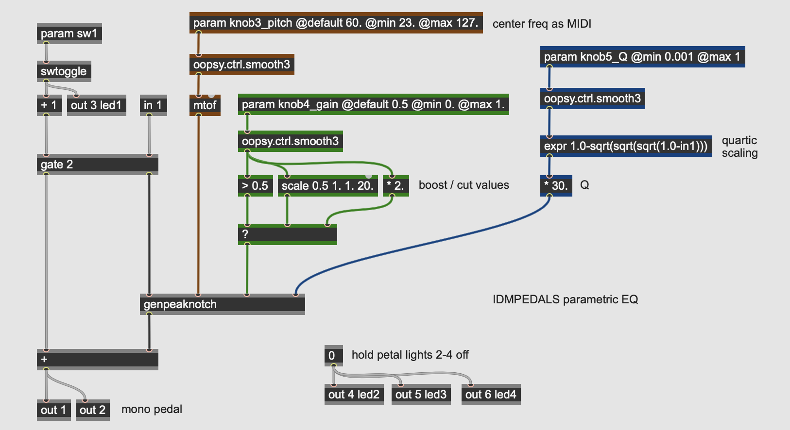
Looking at the main gen~ patcher for the effect, the three parameters (assigned to the param operators) come into the patch, after some smoothing and scaling, send values into the genpeaknotch subpatch.
- knob3_pitch controls the center frequency of the filter; as with the lowpass example above, its value is initially expressed as a MIDI pitch as an easy way to get pitch-linear scaling on the knob control. After smoothing with an oopsy.ctrl.smooth3 abstraction, it is converted to frequency with the mtof operator.
- knob4_gain controls the boost or cut of the filter. The knob brings in a value from 0.0 to 1.0 which is then sent into a ? operator, which works as a ternary conditional (if - then - else) statement. If the value at the left inlet evaluates as true (i.e. non-zero), the second inlet will be passed; otherwise, the third inlet will be passed. So if the gain knob is above 0.5, the filter gain is set to a value between 1.0 and 20.0 using the scale operator; this results in a boost in the filter. If the parameter is below 0.5, the knob’s value gets multiplied by 2.0, outputting a value between 0.0 and 1.0; this results in a cut in the filter.
- knob5_Q controls the filter “quality factor”, which expresses the width of the filter. A filter with a Q of 1.0 has a bandwidth equal to its center frequency; higher Q values narrow the bandwidth relative to the center frequency, and values less than 1.0 mean that the filter bandwidth is wider than the center frequency. The Q parameter here is in the range of 0.03 (very wide) to 30.0 (a very tight filter - 1/30th of the center frequency). The parameter knob comes into the patcher in the range of 0.001 to 1., which after smoothing is then put through a quartic scaling expression. This expression operator keeps the range of the parameter but changes its curvature, resulting in much more fine control at the upper range of the parameter. This value is then multiplied by 30.0 to yield the final Q parameter.
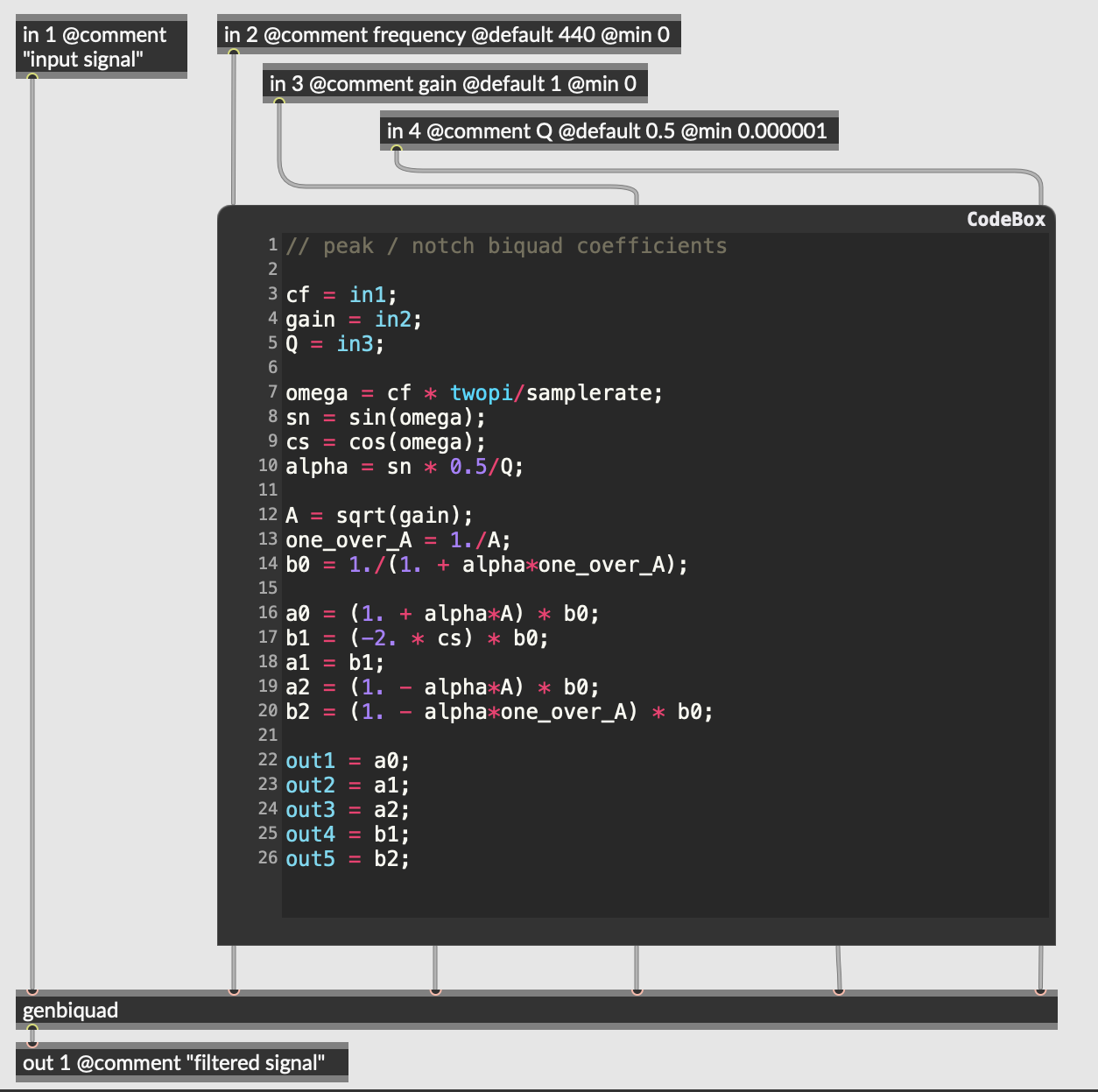
The peaknotch subpatch takes the audio signal and the three parameters from the pedal’s knobs (center frequency, gain, and Q) and calculates the coefficients for a biquadratic filter that does that actual processing on the signal. It does this using a codebox with GenExpr code, running the following calculations:
y[n] = ax[n] + bx[n-1] + cx[n-2] - dy[n-1] - ey[n-2]
where...
x = the input signal
y = the output signal
n = time (n is now, n-1 is one sample ago, etc.)
Fc = cutoff frequency
G = gain
Q = quality factor
SR = sampling rate

Ω = Fc * 2π/SR (sampling increment)
alpha = sin(Ω) * 0.5/Q

A = sqrt(G)
B = 1./(1. + alpha*1.0/A)

a = (1. + alpha*A) * B
b = c = (-2. * cos(Ω)) * B
d = (1. - alpha*A) * B
e = (1. - alpha*1.0/A) * B
The outputs of the codebox are the five biquad coefficients.
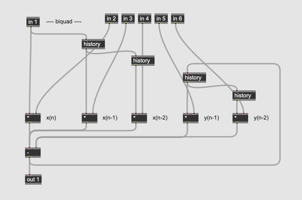
The genbiquad subpatch implements the biquadratic filter equation on the input audio stream (in 1) using the five coefficients calculated by the codebox in the parent patcher. The nested history and arithmetic operators perform the calculations.
Parametric equalizers have advantages over fixed-band equalizers (such as found in graphic equalizers) insofar as they allow you to sweep and tune the filter to the specific frequency you like. This allows you to, e.g. notch out a specific resonance in the input signal or emphasize a specific range of frequencies by ear.
EQ: Fixed Crossover Filter
More Info...
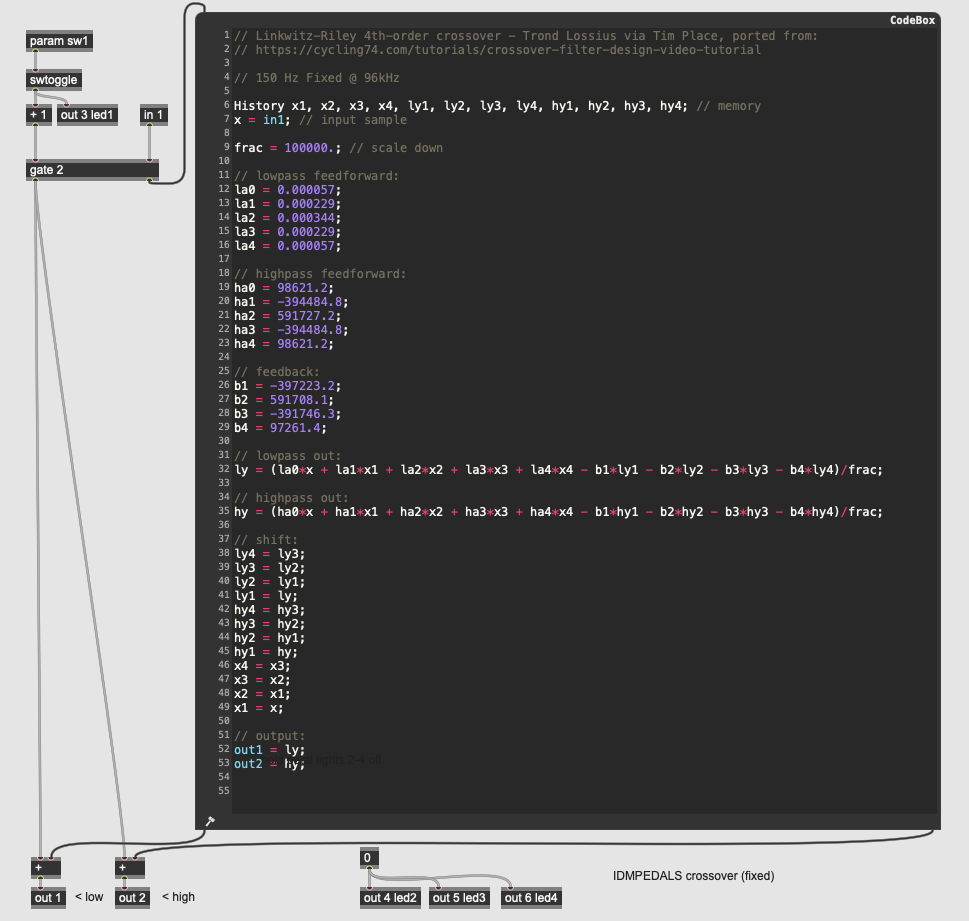
This pedal demonstrates how to implement a crossover filter as a stereo output on a pedal. Crossovers are important utility filters in signal processing, as they allow you to process different frequency bands independently and then recombine them later. This particular crossover filter has no parameters at all - it works with a fixed crossover frequency of 150 Hz, with frequencies below the cutoff going to the first output and frequencies above the cutoff going to the second output.
This gen~ patcher also demonstrates how to do signal processing completely within a codebox, using GenExpr code adapted from Tim Place’s crossover filter design tutorial. All of the gen~ operators are available within the GenExpr language, including a History data type which can be declared at the top to allocate memory.
The crossover algorithm used in this pedal is a Linkwitz-Riley crossover - a 4th-order filter which creates a sharp (but low-ripple) division between frequencies on either side of the center frequency. It uses both feedforward and feedback delay stages (for both the low and high outputs), making it an infinite impulse response (or IIR) filter.
Hint: when working with the Electrosmith Daisy as a target for gen~ patches, you sometimes need to accommodate for the fact that the Daisy microcontroller is a 32-bit architecture, as opposed to a 64-bit general computing platform such as a Mac or Windows desktop machine. In the case of this patch, you can see the frac variable at the top, which is used at the bottom as a divider for all the coefficients. This allows the coefficients to be written six decimal points higher than usual, giving the internal calculations a higher degree of accuracy in the 32-bit floating-point range.
EQ: Variable Crossover Filter
More Info...
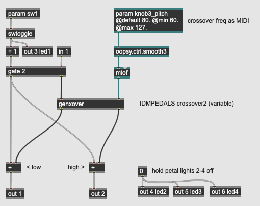
This pedal expands on the previous one, adding a single parameter for the crossover frequency. As with the lowpass and parametric EQ pedals, this algorithm uses MIDI scaling for the knob control, smoothing and converting it before sending it into the genxover subpatch:
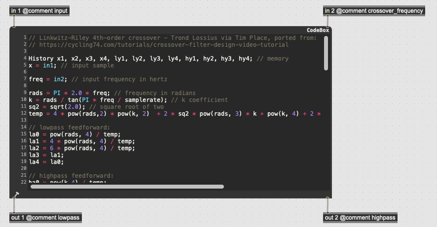
This subpatch contains a codebox with GenExpr code to calculate and perform the crossover on the input signal. The algorithm, written by Tim Place in his crossover filter design tutorial, implements a Linkwitz-Riley crossover filter with a variable crossover frequency, so there is significantly more code in this GenExpr than the one above - this is because the filter coefficients need to be calculated on the fly in response to the crossover frequency parameter, which could change at any time.
EQ: Envelope Wah
More Info...
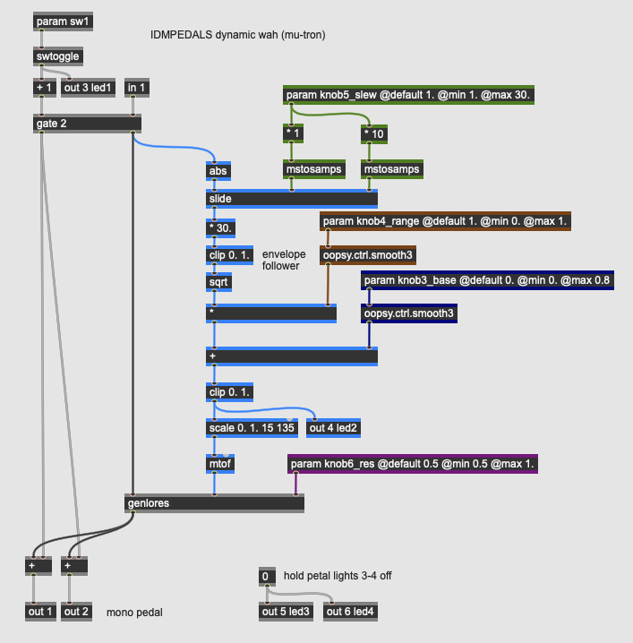
This pedal is a wah-wah algorithm where the position of the filter is controlled not by an expression pedal but by the amplitude of the input signal, via an envelope follower. This technique was first used to great acclaim in the 1972 Mu-Tron III envelope filter.
The algorithm in this pedal has four parameters:
- knob3_base sets the fundamental (bottom) frequency of the wah effect, brought in as a value from 0.0 to 0.8; this maps to 0% to 80% of the range of the filter, later scaled to MIDI.
- knob4_range sets the range of the input signal’s amplitude on the wah, ranging from very subtle to covering the entire range of the filter.
- knob5_slew sets the attack/release characteristics of the envelope follower algorithm, with a low value causing the envelope to closely track the input signal, and a high value generating a smoother - but less responsive - control value.
- knob6_res sets the resonance of the wah itself, with higher values creating a stronger peak at the cutoff frequency.
The envelope follower algorithm in the pedal follows the path colored blue in the patcher: it takes the input signal, rectifies it with the abs operator to set the values positive, and then lowpasses the signal using the slide operator. The second and third inlets of the slide operator control the denominator of the filter in the rising and falling direction, respectively, with higher values making smoother output values; the values for the operator are controlled by knob5_slew. This rectified and lowpassed value is then scaled up, clipped in the range of 0.0 to 1.0, and finally transformed into an exponential signal using a sqrt operator. This value is the final envelope signal.
Once the input signal’s envelope is calculated, the value is multipled by knob4_range and offset by knob3_base to generate a signal that controls the cutoff frequency of the wah. It also illuminates led2 on the Daisy Petal board. Before going into the genlores subpatch, this value is converted to frequency by scaling the value to a MIDI range and then to Hertz using the mtof operator.
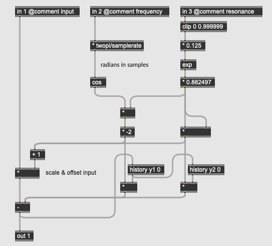
The actual wah effect in this pedal consists of a 2nd order, resonant lowpass filter solved by the calculation in the genlores subpatch pictured above:
y[n] = ax[n] - by[n-1] - cy[n-2]
where...
x = the input signal
y = the output signal
n = time (n is now, n-1 is one sample ago, etc.)
Fc = cutoff frequency
R = resonance value
SR = sampling rate

Ω = Fc*2π/SR (sampling increment)
G = e^R*0.125 * 0.882497 (resonant coefficient)

c = G*G
b = -2.0*cos(Ω)*G
a = 1.0 + b + c
As with the Mu-Tron III that inspired this design, this pedal will respond the the dynamic range of the input instrument by opening the filter on louder notes. The different controls allow you to fine tune both the range and resonance characteristics of the wah itself as well as - just as importantly - the slew of the envelope follower. The original Mu-Tron pedals used a Vactrol with its characteristic response curve to couple the envelope follower to the filter; the photoresistor replaced the potentiometer that would have been attached to the rocker pedal on a conventional wah.
EQ: Auto-Wah
More Info...
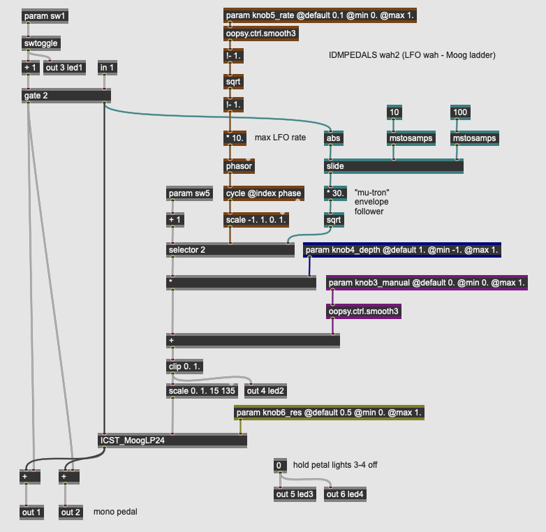
This pedal uses the same premise as the last - a wah-wah controlled by something other than a rocker pedal, and builds it out so that the wah frequency can be controlled by an low frequency oscillator (LFO). It also has a (simplified) version of the Mu-Tron-style envelope follower in the previous pedal that can be activated with a switch. The filter in this pedal is more complex as well: instead of a 2nd order lowpass filter, the filter is Peter McCulloch’s implementation of the Moog Ladder Filter.
Like the Mu-Tron-style wah, this pedal has four parameters:
- knob3_manual sets the center frequency of the wah effect, brought in as a value from 0.0 to 1.; the LFO then oscillates above this setting; when the LFO depth is set to 0.0 the filter will be fixed at this so-called manual value.
- knob4_depthe sets the amplitude of the LFO, which is then added in to the manual setting.
- knob5_rate sets the rate of the LFO from 1 to 10 Hertz. The input knob outputs values from 0.1 to 1. which are put through an exponential scaling function by inverting the value, taking its square root, and then inverting it again. This gives more control bandwidth to the lower (slower) values.
- knob6_res sets the resonance of the wah itself, with higher values creating a stronger peak at the cutoff frequency.
Finally, the pedal design uses a toggle switch (param sw5) to disengage the LFO via the selector operator and use a simplified envelope follower from the previous pedal (colored in green in the patcher) to create an envelope filter effect.
The LFO is a sine wave oscillator generated by a cycle operator set in phase index mode, which allows it to be driven directly by a phasor operator. This phasor generates the core LFO based on the smoothed and scaled output of knob5_rate. The sine wave is mapped to the range of 0 to 1. The selector operator (controlled by sw5) switches between the LFO output and the envelope follower, which uses a slide operator to smooth the absolute value of the input signal.
The output of the LFO / envelope follower is then amplified with the depth parameter and offset with the manual parameter. This final signal controls the cutoff frequency of the wah. It also illuminates led2 on the Daisy Petal board. Before going into the ICST_MoogLP24 subpatch, this value is converted to frequency by scaling the value to a MIDI range.
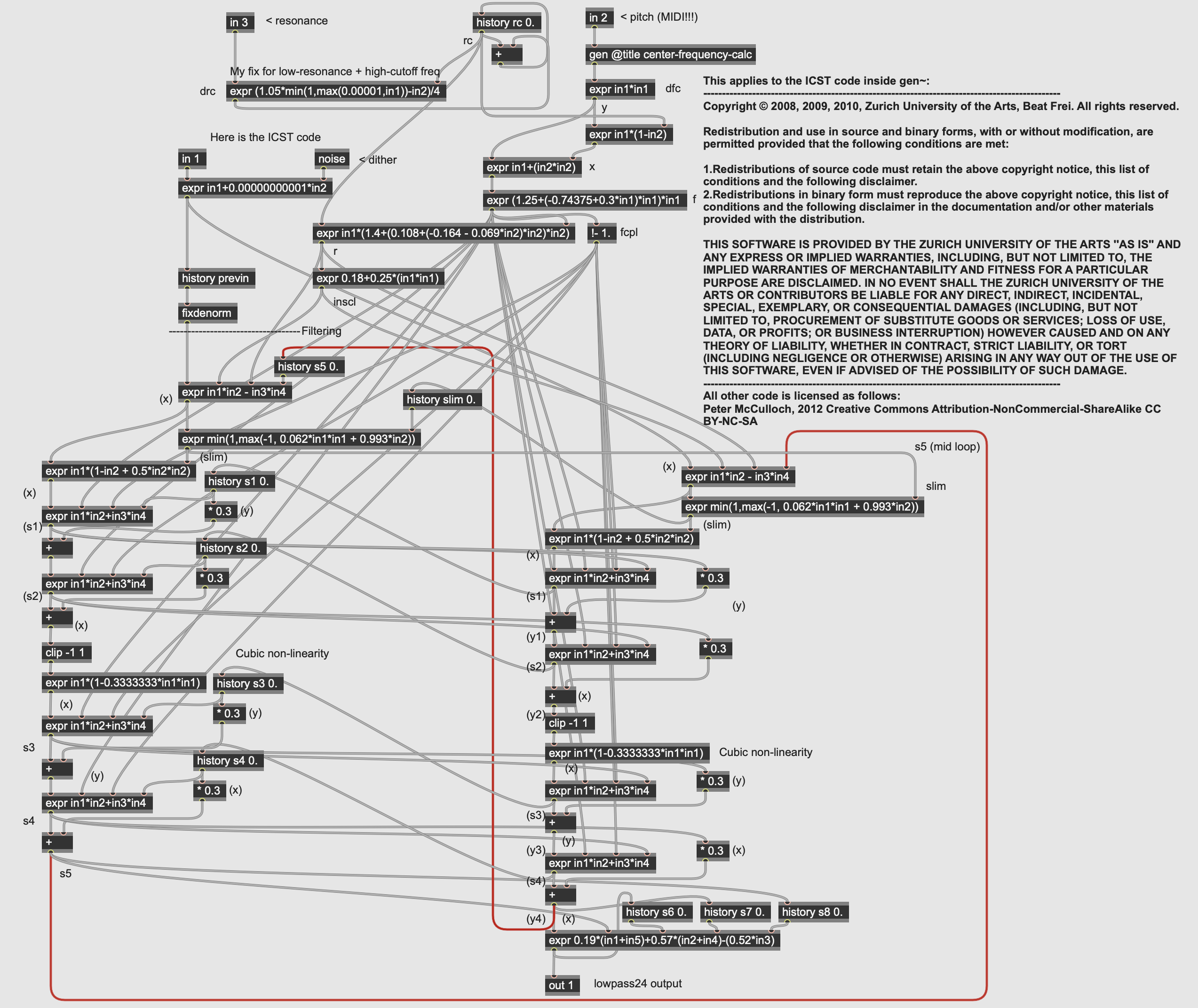
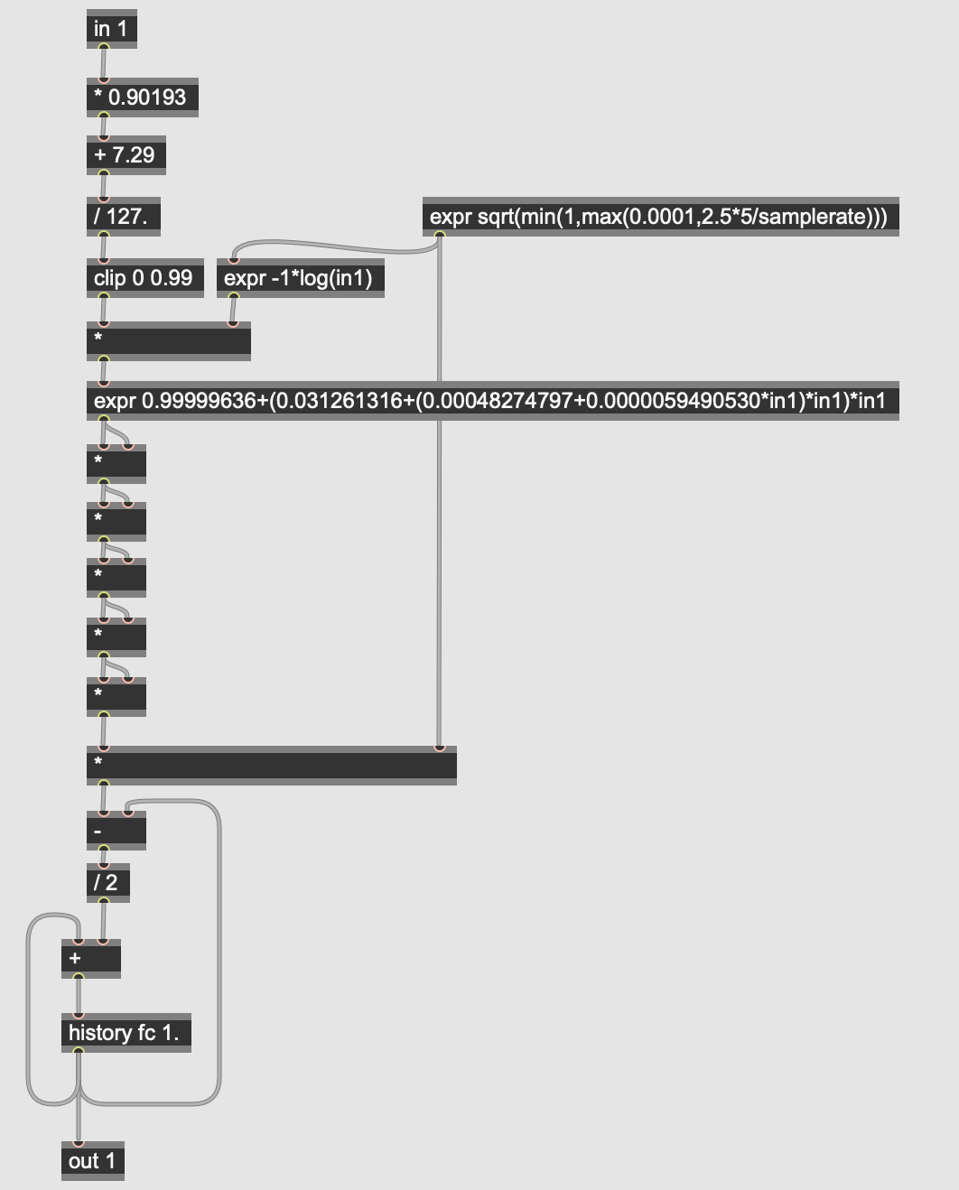
The ICST_MoogLP24 subpatch implements a digital model of the classic 4-pole resonant low-pass “Ladder Filter” developed by Robert Moog for his synthesizers. This filter has a 24dB roll-off and can resonate to the point of self-oscillation. One thing of note is that the filter module is modelled even to the point of using Moog’s 1V / Octave scaling to represent frequency; as a result, the incoming pitch value is converted into this range using the center-frequency-calc subpatcher:
Auto-wah effects - where the filter is controlled by the input signal’s envelope or by an LFO, are common effects, and the underlying algorithms for designing the envelope followers and oscillators can be used with many other types of processing.
EQ: Formant Filter
More Info...
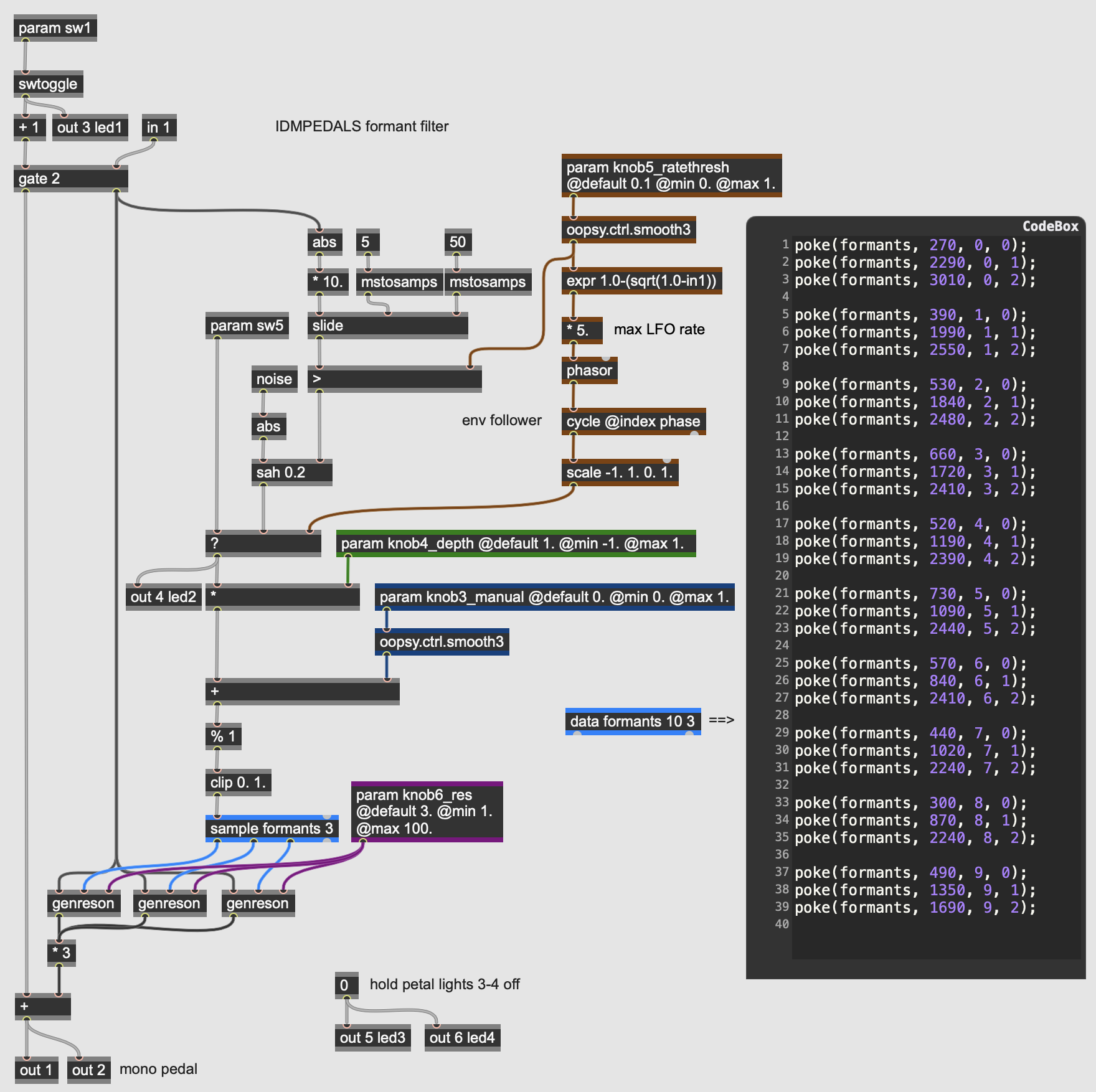
This pedal implements a filter that simulates the formants of the human vocal tract. Unlike a conventional filter effect where the key aspect of the filter is its center or cutoff frequency, a formant filter contains an array of values that represent different vowel sounds, using three resonant bandpass filters. These vowels are then scanned as a continuum that can be indexed either by an low frequency oscillator or an envelope follower, as per the previous pedals.
The control parameters for the formant filter pedal are similar to the auto-wah:
- knob3_manual sets the center formant of the filter effect, brought in as a value from 0.0 to 1.; the LFO then oscillates above this setting; when the LFO depth is set to 0.0 the filter will be fixed at this so-called manual formant.
- knob4_depth sets the amplitude of the LFO, which is then added in as a bipolar signal to the manual setting.
- knob5_ratethresh sets both the rate of the LFO from 1 to 5 Hertz, and the threshold for the envelope follower to trigger a new formant. Unlike the previous two filter examples where the envelope of the input signal sweeps the filter range, here a threshold value triggers a new random formant using the noise and sah (sample-and-hold) operators; every time the input signal rises above the threshold value set by this knob, a new random control value will change the sound of the filter.
- knob6_res sets the resonance of the formant filter itself as a Q (quality) factor, with higher value resulting in a narrower bandpass effect.
- sw5 selects between the LFO and the envelope follower as the control source for the formant filter.
The formant filter differs from the other filter effects we’ve looked at: rather than the LFO or envelope driving a scaled value that serves as the filter’s frequency, this filter uses a simple database of formant frequencies stored into a data operator in the gen~ patcher. The data operator in gen~* works in a manner similar to the buffer~ object in Max/MSP - it can store an arbitrary set of numerical values across a number of channels. In this case, the operator in the patcher data formant 10 3 declares a dataset in memory labelled “formant” that will have 10 indices with three values (stored in what are called channels) stored at each index. This is akin to a 2-dimensional, 10-value array in a programming language where each value in the array is itself an array of length 3.
The codebox on the right of the patcher initializes all the values in the “formant” data operator. The poke command in GenExpr sets triplets of values into the channels. Each index in “formant” consists of the three fundamental frequencies for a vowel in the English language.
Once the dataset we want to work with is stored into the data operator, it can be read and used in the algorithm. The sample operator (colored in blue) indexes the “format” data using the LFO/envelope values from 0.0 to 1.0 - a value of 0.0 will output the first indexed values; a value of 10.0 will output the last indexed values, and numbers in between will interpolate between the rest of the data. The sample operator is multi-channel, so all three of the formant filters can be driven with one sample. These frequencies (along with the input signal and the param knob6_res parameter then go into three parallel genreson subpatches that perform the filtering on the input signal:
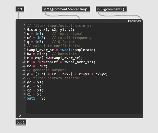
This subpatch implements a 2nd order resonant bandpass filter, equivalent to the reson~ object in Max/MSP:
y[n] = ax[n] + bx[n-2] + cy[n-1] + dy[n-2]
where...
x = the input signal
y = the output signal
n = time (n is now, n-1 is one sample ago, etc.)
Fc = center frequency
Q = resonance value (Q factor)
SR = sampling rate

bw = Fc/Q (bandwidth)
r = e^-bw*2π/SR (sampling increment)

a = 1-r
b = (1-r)*r
c = 2*r*cos(Fc*2π/SR)
d = -r*r
The three reson filters, when run in parallel, simulate the resonances of the human mouth when forming basic vowel sounds - roughly speaking, each filter is responsible for the mouth’s width, heigh, and depth. The resulting effect sounds less like a wah-wah and more like a talk box. Formant filtering can be used for many applications, from vocal effects to simulating the resonances of instrument bodies (c.f. the Boss “Acoustic Simulator” pedal).
EQ: Vocoder
More Info...
This pedal implements a Vocoder. Vocoders were originally developed as a mechanism for low-bandwidth (and secure) encoding of speech as parallel streams of envelopes (DC voltages) that could be transmitted and resynthesized at their destination. These devices became used creatively by composers and musicians so that by the 1970s vocoders were being manufactured (by Moog, Roland, and others) exclusively for use as a musical cross-synthesizer, allowing two audio sources to be blended, with one source providing the tonal characteristics and the other providing the articulation and timbre.
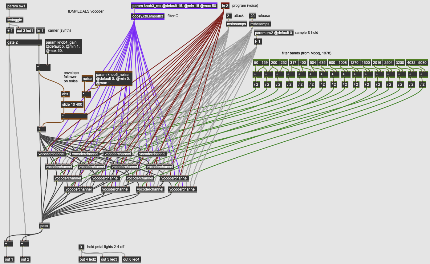
The patcher used here implements a vocoder based on the [1978 16-channel Moog Vocoder]. It uses two inputs, with input 1 serving as the carrier (typically a tonal input such as a synthesizer) and input 2 serving as the program (typically an input with a rich, articulated spectrum such as voice). The effect works by filtering both inputs using a bank of bandpass filters; it then puts the output of each of the program’s filter channels through an envelope follower; these envelope characteristics are then used, channel-by-channel, to control the gain of the equivalent frequency band in the carrier sound. The result is a synthesizer than can sound like its talking, for example.
Our vocoder effect has three parameters and one switch used to control the effect:
- knob3_res controls the Q of the filters in both sides of the vocoder; the higher the Q, the more focused both the analysis (program) and synthesis (carrier) channels will be on the center frequencies of the 16 filter bands used in the effect.
- knob4_gain controls the volume (gain) of the carrier input.
- knob5_noise controls a white noise signal that can be mixed in with the carrier to give it more spectral density. A high amount of noise will make the vocoder sound raspier and more voice-like.
- sw2 is a momentary “hold” switch will freeze the envelope states of the program signal. This allows you to, e.g. sing a vowel and sustain it as the filter effect with a footswitch.
The vocoder algorithm takes the carrier (in 1, mixed with noise based on knob5_noise) and the program (in 2) and sends both signals (along with parameter information) into sixteen parallel instances of the vocoderchannel subpatch. These subpatches are identical but receive different center frequency settings at their second inlets.
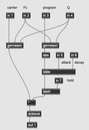
The sixteen individual vocoderchannel subpatchers perform three tasks:
- filter both the carrier and program inputs based on the center frequency and Q sent in from the parent patcher. The frequencies are based on the 1978 Moog specification and are different for each subpatcher; the Q is set by knob3_res. The algorithm for the filter is a 2nd order resonant bandpass (genreson, the same as used in the formant filter example).
- an envelope follower is applied to the program signal, with abs and slide operators generating a positive envelope signal for each filter channel of the program. This value can be sustained by sw2, which connects to the latch operator to hold a constant value.
- a multiplier that takes the filtered audio of the carrier signal and multiplies it by the envelope derived from the filtered program signal. This, happening across sixteen parallel bands, is the heart of the vocoder effect. The dcblock operator removes any unwanted sub-audio signal from each channel.
The sixteen outputs of the vocoderchannel are then summed to the output of the pedal.
As with the formant filter, the vocoder channels implement a 2nd order resonant bandpass filter, equivalent to the reson~ object in Max/MSP:
y[n] = ax[n] + bx[n-2] + cy[n-1] + dy[n-2]
where...
x = the input signal
y = the output signal
n = time (n is now, n-1 is one sample ago, etc.)
Fc = center frequency
Q = resonance value (Q factor)
SR = sampling rate

bw = Fc/Q (bandwidth)
r = e^-bw*2π/SR (sampling increment)

a = 1-r
b = (1-r)*r
c = 2*r*cos(Fc*2π/SR)
d = -r*r
The vocoder is an interesting hybrid processor, using a filter bank not for traditional equalization, but as a multi-band dynamics processor where a second signal controls the gain on each channel. In the next section, we consider dynamics effects, many of which use this technique for different common effects in music production.
Dynamics
Dynamics effects work by changing the gain of the input signal. Dynamics-based processing techniques, like equalization, are central to audio production, and effects such as compression, limiting, and noise gates are used in live sound reinforcement, broadcast engineering, recording, and mastering, as tools to help create consistent output levels, prevent sudden signal spikes, reduce noise, and generally improve signal quality. Generally, one important common factor in dynamics processing is the generation of a key signal, usually via an envelope follower; this signal gives the rest of the circuit an understanding of the overall volume of the input, which then influences how the real signal is attenuated or amplified. In pedal design, dynamics processors are often first in the effects chain to provide compression on the instrument signal, levelling its dynamic range, or gating to reduce noise. With these algorithms, creative effects are possible, often by using sidechain inputs for the key signal.
Dynamics: Tremolo
More Info...
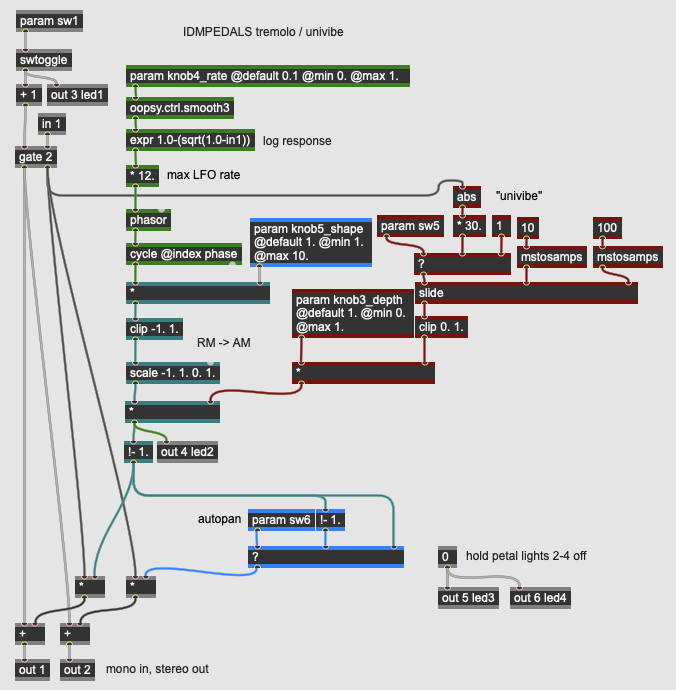
This pedal implements one of the oldest dynamics-related effects: a periodic fading-in and fading-out of the signal through amplitude modulation that creates an effect akin to musical tremolo. The tremolo effect uses a low frequency oscillator (LFO), which can be shaped from a sine wave to a near-square wave. The effect has a switch that allows the intensity (depth) of the effect to be controlled with by a constant knob value or by the amplitude of the input signal; this latter technique is inspired by the classic Uni-Vibe pedals from the 1960s. Finally, this pedal has a stereo output, allowing it to be used as an auto-panner.
The pedal has three knob controls as well as two switches that control its configuration:
- knob3_depth sets the manual intensity of the tremolo effect when sw5 is disengaged. When turned all the way up, the input signal will be completely attenuated when the LFO is at its lowest point.
- knob4_rate sets the speed of the LFO up to 12 Hz; the knob has a logarithmic response through the use of the expr operator.
- knob5_shape alters the waveform of the LFO by amplifying it into a clipping circuit. This allows the shape of the tremolo to range from a smooth sine wave to an extreme in/out shape by making the LFO close to a square wave.
- sw5 selects between knob3_depth and the envelope follower as the intensity control of the LFO.
- sw6 engages an auto-panning effect where the LFO is inverted at the right output; with this setting engaged, the pedal has a stereo output where the gain of the signal in the left channel will be the opposite of the right.
As with the Wah effects above, this effect uses both an LFO and, optionally, an envelope follower to adjust the actual effect, which is simply a gain control using a * operator. The LFO is a cycle operator driven by a phasor that can be shaped through a gain stage into a clip operator; this shapes the waveform according to knob5_shape. The envelope follower takes the input signal and converts it into a smooth representation of the input gain using the abs and slide operators. The intensity of the tremolo effect illuminates led2 on the Daisy Petal board.
Tremolo effects are among the oldest special effects for instruments, with tremulant effects on organs as far back as the 18th Century. Modern tremolo pedals are often categorized as modulation effects (alongside flangers, phasers, etc.) but we consider them here alongside other dynamics processors as algorithms that modify the volume of a signal.
Dynamics: Compressor/Limiter
More Info...
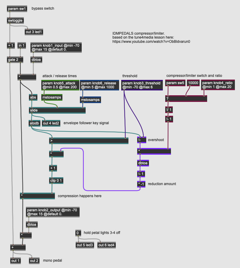
The pedal implements a digital compressor / limiter, where an input signal exceeding a threshold value is attenuated either by a fixed ratio (compression) or by a very high ratio guaranteed to keep the audio within a specific dynamic range (limiting). Compressors and limiters, in addition to their threshold and ratio settings, also have controls around how quickly the compression takes effect when the threshold is exceeded (the attack time) and how quickly the compression relaxes once the input signal goes below the threshold (the release time); in practice, both of these parameters are controlling aspects of the envelope follower that generates the key signal for the dynamics processor. Finally, most compressor / limiters allow the user to adjust both the input gain into the circuit and the output level (sometimes called makeup gain).
This particular compressor / limiter is inspired by the tune4media lesson on compression using gen~ found here.
In light of all these parameters, our compressor pedal has six dynamic controls and one switch:
- knob1_input sets the level of the input signal into the compression circuit; this allows us to fine tune the compressor to work with a wide range of instrument inputs. This value range is in decibels, with the eventual value converted to linear amplitude using the dbtoa operator.
- knob2_output sets the output of the pedal, post-effect, in the same manner as the knob1_input. Compression circuits often refer to this parameter as the makeup gain of the circuit, as the compressor itself only reduces the volume. This allows you to get a louder overall signal by compressing the input and then boosting the overall output.
- knob3_threshold sets the level at which the compressor / limiter engages. It does this by comparing its value against the output of the input signal’s envelope follower. To maintain a logarithmic response, all of these calculations occur in decibels.
- knob4_ratio sets the amount of compression applied to the signal as it rises above the threshold; a ratio of 1:1 means no compression; a ratio of 2:1 means that the input signal needs to rise 2 decibels above the threshold for every 1 decibel of rise out of the compressor. Higher ratios cause more compression; when the limiter sw5 is engaged, this ratio is ignored.
- knob5_attack sets the attack time (in milliseconds) for the compressor to engage; this is the rising value for the slide operator on the input signal’s envelope follower. A fast attack will cause the compressor to engage quickly in response to fast dynamic changes.
- knob6_release sets the release time (in milliseconds) for the compressor to disengage; this is the falling value for the slide operator on the input signal’s envelope follower. A slow release will cause the compressor to slowly relax its attenuation.
- sw5 selects between the circuit behaving as a compressor, where the ratio set by knob4_ratio is used, and a limiter, where a very high (10000) ratio is used. When engaged, the input will never exceed the threshold value, creating a hard ceiling for the signal’s dynamic range.
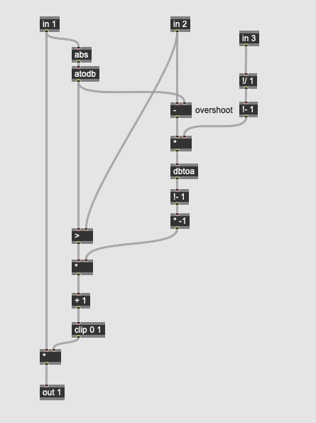
The key signal of the compressor illuminates led2 on the Daisy Petal allowing you to see the behavior of the attack and decay settings. The compressor / limiter’s calculation algorithm works by converting the envelope follower’s output into a key signal expressed in decibels (via the atodb operator); when this value exceeds the threshold (the > operator), the reduction amount calculated by the patcher logic colored purple is engaged to create a multiplication factor on the input signal. The output level knob2_output then adds makeup gain to the signal allowing you to boost the compressed audio.
Compressor / limiters are fairly ubiquitous as pedal effects, particularly with instruments that have high dynamic range in their transients (e.g. electric bass guitars). They can be configured to create a transparent “levelling” of an input signal or be used more creatively to create a hard pumping sound as they engage and disengage.
Dynamics: Noise Gate
More Info...
A noise gate is a dynamics processor that is the inverse of a limiter. Instead of reducing the volume of an input signal that exceeds a threshold, the circuit reduces the volume of a signal that falls below a threshold. This can clean up a signal by eliminating ground hum, hiss, or other low level noise in a signal when the instrument driving the signal is silent. Noise gates, like compressors, are used extensively in audio production beyond effect pedals; their most common use is to attenuate (or duck) background noise in broadcast or recording scenarios where there is an open mic.
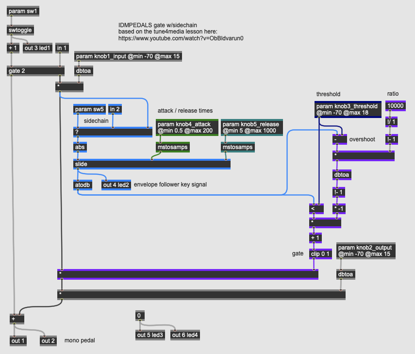
Our noise gate pedal has the same core architecture as the compressor / limiter pedal, with one key component (the comparator operator) changed. There are five dynamic controls as well as a switch that engages the second input to the pedal as a sidechain:
- knob1_input sets the level of the input signal into the gate circuit; this allows us to fine tune the gate to work with a wide range of instrument inputs. This value range is in decibels, with the eventual value converted to linear amplitude using the dbtoa operator.
- knob2_output sets the output of the pedal, post-effect, in the same manner as the knob1_input. Dynamics circuits often refer to this parameter as the makeup gain.
- knob3_threshold sets the level at which the gate engages. It does this by comparing its value against the output of the input signal’s envelope follower. To maintain a logarithmic response, all of these calculations occur in decibels.
- knob4_attack sets the attack time (in milliseconds) for the gate; this is the rising value for the slide operator on the key signal’s envelope follower. A fast attack will cause the gate to duck quickly in response to a note stopping, for example.
- knob5_release sets the release time (in milliseconds) for the gate; this is the falling value for the slide operator on the key signal’s envelope follower. A slow release will cause the ducking effect to slowly fade the input signal back in.
- sw5 selects between the gate listening to the input signal or to a sidechain input at in2 as its key signal; when a sidechain is activated, the gate can be used creatively to, e.g. duck a sustained instrument input based on a drum track.
The key signal’s envelope illuminates led2 on the Daisy Petal allowing you to see the behavior of the attack and decay settings. The gate’s calculation algorithm works by converting the envelope follower’s output into a key signal expressed in decibels (via the atodb operator); when this value falls below the threshold (the < operator), the reduction amount calculated by the patcher logic colored purple is engaged to create a multiplication factor on the input signal; this will attenuate quiet signals to 0 when the gate fully engages. The output level knob2_output then adds makeup gain to the signal allowing you to boost the compressed audio.
Noise gates are used as pedal effects to help attenuate electrical hum (e.g. from a single-coil guitar pickup) and other unwanted sounds when an instrument goes quiet; they are also used with sidechain inputs to add rhythmic effects to a sound.
Distortion
Distortion effects are some of the most iconic signal processing techniques used in audio, and some of the earliest effect pedals fall into this category. Like dynamics effects, distortion effects are mathematically adjusting the amplitude of an audio signal; however, unlike dynamics effects, where the objective is to control the sound’s dynamic range overall, distortion effects directly alter the sound wave of the input signal through techniques such as clipping, waveshaping, and other mathematical algorithms that simulate the characteristics of amplification equipment being fed a hot signal, pushed beyond their recommended power output, or intentionally damaged. Modern distortion effects depart from the historical categories of fuzz, overdrive, and distortion to create new sounds, all of which shape the input signal in way that its timbre is transformed.
Distortion: Overdrive
More Info...
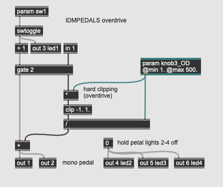
This pedal implements a simple distortion algorithm called hard clipping, where a signal is amplified, then input into a circuit that imposes a hard limit on its range, causing an overdrive effect where the waveform squares off at the edges, emphasizing and adding harmonics to the signal. Using analog circuitry, hard clipping is easily accomplished by overdriving an operational amplifier; with DSP, we can accomplish a similar effect with one parameter (knob3_OD) that amplifies the input signal (using a *) into a clip operator (shaping the signal), then divides the signal back down to lower the overall volume (using a /). The higher the overdrive factor (up to 500 in our algorithm), the more prominent the clipping effect will be.
Distortion: Fuzz
More Info...
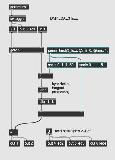
This pedal implements a more extreme distortion effect by creating sharper angles in a waveform by calculating the hyperbolic tangent of the input signal. This fuzz effect (done using transistor feedback in analog circuits) emphasizes high harmonics. The single parameter for our pedal (knob3_fuzz) amplifies the input signal (using a *) into the tanh operator; the output is then constrained using the clip operator and then divided down (using a /) by 1/10th of the input gain to level the output volume.
Distortion: Octave Fuzz
More Info...
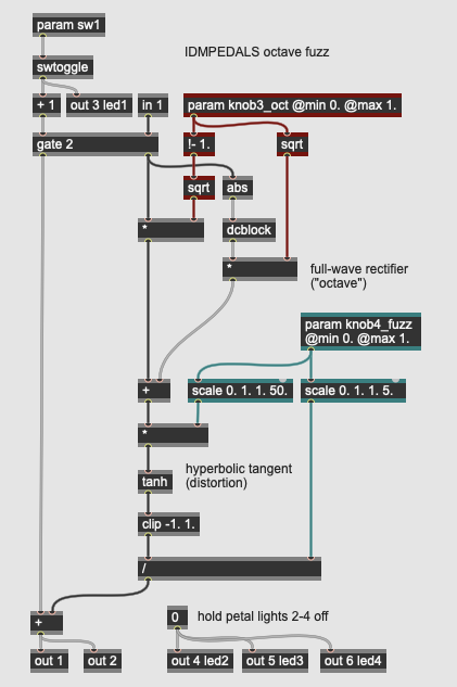
This pedal implements an octave fuzz such as found in the Octavia pedal designed by Roger Mayer for Jimi Hendrix. An octave fuzz uses a rectifier circuit to fold the negative side of the AC waveform over into the positive range; this has the effect of doubling the frequency of the input signal, raising the fundamental by an octave. This type of pitch shifting through full-wave rectification works, though the sound can be fairly rough due to slope of the signal near the fold-over point. The output of the rectified signal is then put into a fuzz circuit.
Our digital octavia pedal has two parameters: knob3_oct controls the blend of the octave effect with the dry signal. The octave effect is accomplished by using the abs operator (to rectify the signal) and the dcblock operator (to rebalance the rectified signal into the AC range). The blending of the dry and octave signal is done through an equal-power fade.
The second parameter (knob4_fuzz) controls the amount of the fuzz effect using the same algorithm as the previous pedal : a signal multiplied into a hyperbolic tangent operator (tanh) with a clipped output (clip). The result is a fuzzed version of the blended octave signal.
Distortion: Amp Distortion
More Info...
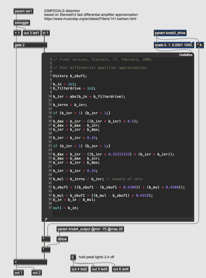
This pedal simulates classic amp distortion using a DSP algorithm developed by Randy Stenseth to model the response of a fast differential amplifier. The two parameters control the “filterdrive” coefficient for the amplifier algorithm (knob3_drive) and the overall output gain (knob4_output). The bulk of the effect is accomplished by the GenExpr code in the codebox, which implements the Stenseth algorithm:
// Final version, Stenseth, 17. february, 2006.

// Fast differential amplifier approximation

History b_sbuf1;

b_in = in1;
b_filterdrive = in2;

b_inr = abs(b_in * b_filterdrive);

b_inrns = b_inr;

if (b_inr > 1) {b_inr = 1;}

b_dax = b_inr - ((b_inr * b_inr) * 0.5);
b_dax = b_dax - b_inr;
b_inr = b_inr + b_dax;

b_inr = b_inr * 0.24;

if (b_inr > 1) {b_inr = 1;}

b_dax = b_inr - ((b_inr * 0.33333333) * (b_inr * b_inr));
b_dax = b_dax - b_inr;
b_inr = b_inr + b_dax;

b_inr = b_inr / 0.24;

b_mul = b_inrns / b_inr; // beware of zero

b_sbuf1 = ((b_sbuf1 - (b_sbuf1 * 0.4300)) + (b_mul * 0.4300));

b_mul = b_sbuf1 + ((b_mul - b_sbuf1) * 0.6910);
b_in = b_in / b_mul;

out1 = b_in;
Distortion: Multi-Band Distortion
More Info...
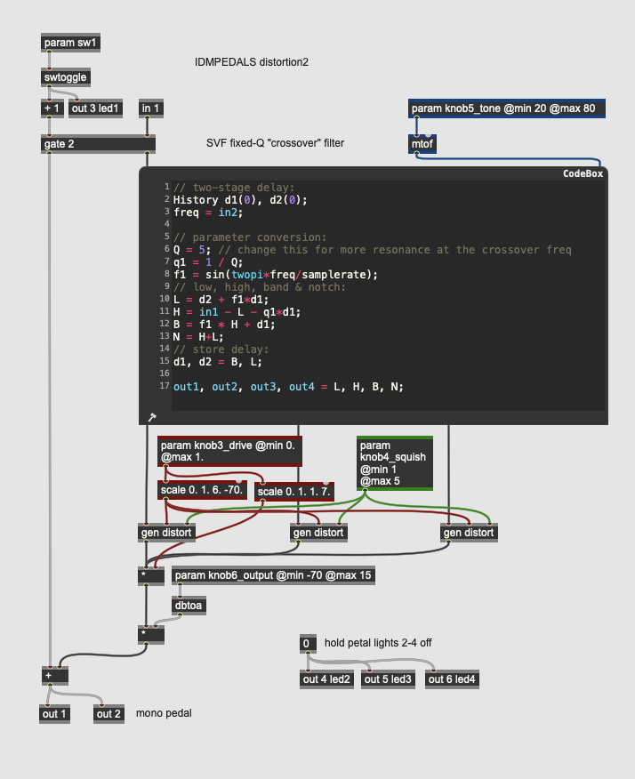
This pedal implements a multi-band distortion where the input signal is split into three frequency bands, each of which is distorted separately using a sample-by-sample compression circuit that functions as a soft clipping overdrive. The effect uses a 2nd-order state variable filter (SVF) to divide the input signal into three bands, with a lowpass, bandpass, and highpass output being treated independently.
The pedal has three parameters:
- knob3_drive controls the threshold of distortion for each of the three frequency bands. This threshold is compared to the input signal directly rather than to a smoothed key signal, so the amplitude transformation occurs on a sample-by-sample basis.
- knob4_squish controls the amount of distortion for each of the three frequency bands. The distortion in our pedal consists of a sample-by-sample attenuation that creates a soft clipping effect.
- knob5_tone controls the crossover frequency of the SVF. The value from the knob is in a MIDI range which is converted to frequency via the mtof operator. The codebox for the SVF contains GenExpr code to implement the following filter:
Fc = center frequency
SR = sampling rate
d1, d2 = two samples of memory
Q = 5 (resonance value)
Ω = Fc*2π/SR (sampling increment)

LowPass = d2 + sin(Ω)*d1
HighPass = in1 - L - 1/Q*d1
BandPass = sin(Ω) * H + d1
Notch = H+L (unused)

d1 = BandPass
d2 = LowPass
The three output bands (lowpass, bandpass, highpass) are then sent into a distort subpatch:
This patcher implements a sample-by-sample soft clipping effect using an algorithm similar to a compressor without the key signal: if the absolute value of the input signal exceeds the threshold set by knob3_drive, it will be attenuated by the knob4_squish amount.
Distortion: Clipping, Folding, Wrapping
More Info...
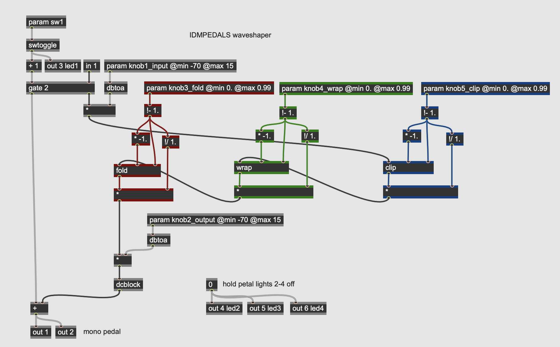
This pedal implements three elementary forms of waveshaping in series on the input signal, with the effect parameters controlling the strength of the effect. Waveshaping of this sort is more common in synthesizers (so-called distortion synthesis) but can be interesting as a signal processing technique as well.
The five parameters for the pedal are:
- knob1_input sets the level of the input signal into the distortion circuit. This value range is in decibels, with the eventual value converted to linear amplitude using the dbtoa operator.
- knob2_output sets the output of the pedal, post-effect, in the same manner as the knob1_input.
- knob3_fold sets the threshold for wave folding distortion applied to the signal using the fold operator; signals that exceed this threshold in either direction (positive or negative) will have their values folded back inwards.
- knob4_wrap sets the threshold for a wrapping (modulo) effect on the signal using the wrap operator; signals that exceed the threshold will wrap around to the negative threshold.
- knob5_clip sets the threshold for signal clipping (the clip operator; signals exceeding this threshold will be truncated at the threshold.
The pedal implements these three distortions in reverse order, so that the signal is clipped, then wrapped, then folded. You can easily repatch the gen~ to do these procedures in a different order to experiment with different sounds.
Distortion: Parametric Waveshaper
More Info...
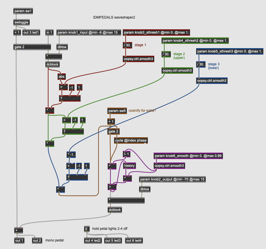
This pedal implements parametric waveshaping on the input signal, where three parameters set threshold values that determine whether a given sample’s polarity is flipped (i.e. a positive sample becomes a negative sample and vice-versa). This will create extreme local discontinuities in the signal that evoke a true “digital” form of distortion.
In our design, each sample’s absolute value is first compared against a threshold (knob3_xthresh1); if it is greater than the threshold value it is inverted. Then, the positive signal values are compared against a second threshold (knob4_xthresh2); again, signals greater than the threshold are inverted. Third, the negative values are compared against a final threshold (knob5_xthresh3), with signals less than the threshold inverted back into the positive rage. Next, this waveshaped signal is sent through an optional circuit (engaged with sw5) which uses the signal values as phase indices of a cycle operator. Finally, the resulting waveform is smoothed out by a simple one pole lowpass filter according to an amount set by knob6_smooth.
In addition to the waveshaping algorithm described above, the pedal has parameters for input and output level (knob1_input and knob2_output).
Modulation
Modulation effects use short, shifting time delays to add depth and richness to a signal, by simulating rotary cabinets (phasers), generating ensemble-like sounds (chorus), or creating moving resonant peaks in the signal (flangers). Modulation effects are among the most creative categories of effects processor, with a wide variety of different techniques and approaches.
Modulation: Simple Chorus
More Info...
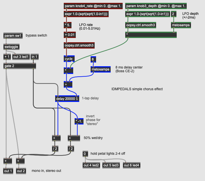
This pedal produces a simple chorus effect by shifting the pitch of the incoming signal up and down via a modulating delay line; this signal is then mixed back in with the original to create the illusion of an ensemble sound. Analog chorus effects were developed to take advantage of bucket brigade devices - inexpensive integrated circuits which allowed for analog delay lines, and became popular as pedals, rackmount studio gear, and as effects integrated into instrument amplifiers. Chorus effects simulate the sound of multiple instruments playing the same line - the small variations in timing and tuning create a more lush sound (e.g. a string orchestra versus a solo violin).
The key gen~ operator behind this pedal is the delay (colored in blue) which, as its name suggests, is a digital delay line, implemented as an array of memory storage where the write pointer moves through in a loop, with the read pointer a certain amount behind - this distance is the actual delay. The arguments to the delay operator are its maximum length in samples and the number of taps (outputs - here only 1). The signal to be delayed goes into the left inlet of the operator; the actual desired delay time is the value in the right inlet.
To create our chorus effect, we have a low frequency oscillator (LFO) in the form of a cycle operator, which generates a sine wave. The LFO’s rate is set by knob4_rate; its depth is determined by the * operator, based on a value set by knob5_depth. This scaled output is then offset by a + operator that provides a central delay time around which the LFO cycles. In our pedal, modelled after the Boss CE-2 Chorus, the delay center is 8ms, with the depth allowing for a maximum of 2ms in either direction (so 6-10ms of delay). The rate of the effect can go from 0.01 to 5.01 Hz. The expr operators after the param inputs provide a logarithmic scaling to the input knobs so that there is more range at the low values than the high values.
The delayed signal is then mixed back in with the dry signal. Our pedal has a stereo effect output by inverting the phase on the right side. Even with one delay line and simple parameters controlling the LFO, the chorusing effect in our pedal is quite flexible.
Modulation: Chorus Ensemble
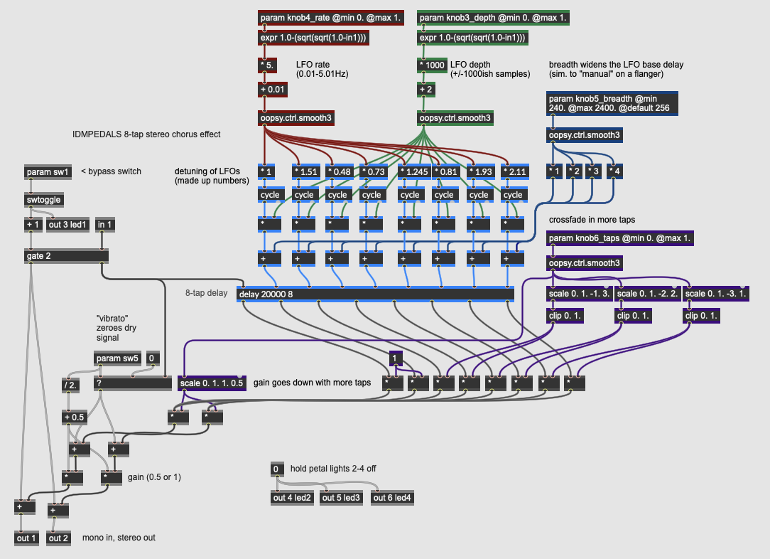
More Info...
This pedal produces a more complex chorus effect than the previous pedal, by using multiple taps on our modulated delay signal. In addition, the central time of the delay can be widened, creating more time delay between the dry and wet signal; this ability to control for breadth as well as depth makes the ensemble effect more flexible. Our pedal design also allows the dry signal to be bypassed entirely, turning the pedal into a vibrato unit.
Our pedal has four continuous parameters as well as one switch:
- knob3_depth controls the depth (amplitude) of the eight LFOs created by the cycle operators in the patch. The depth control goes up to 1002 samples of shift in either direction from the central delay time.
- knob4_rate controls the rate (frequency) of the eight LFOs in the patch. This value is scaled from 0.01-5.01 Hz, and then multiplied by a different value for each of the eight delay taps guaranteeing that the delays will shift around one another; the multipliers into the cycle operators contain values intended to roughly mirror one another in the left and right output channels.
- knob5_breadth changes the base delay of the taps from the delay operator. Each pair of taps has a base delay that is higher than the previous pair, so as the parameter value increases, the delay amounts around which the LFO’s cycle become spread farther apart.
- knob6_taps controls how many delay lines are mixed into the effect signal, with a value of 0 only sounding the first two taps and a value of 1 engaging all 8. This control also sets the overall gain of the effected signal when mixed back in with the original.
- sw5 alternates between a chorus effect - where the delayed and dry signal are combined, and a vibrato effect, where only the wet signal is output.
By using multiple delay taps set to non-integer multiples of one another, this pedal has a much richer chorus effect than the previous example.
Modulation: Flanger
More Info...
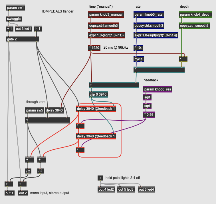
This pedal implements a flanger, a modulation effect that (like a chorus) involves a moving delay line (controlled by an LFO) mixed in with the original signal. Unlike a chorus effect, however, flangers often use a wider range of delay times and feedback to emphasize the resonant effects of the comb filter caused by a short delay with high regeneration. Flangers have their origin in analog tape manipulation - the edge of a tape reel has a “flange” which can be manipulated to slightly vary its speed. Analog pedal-format flangers became popular with the advent of solid state bucket brigade devices which allowed for delay effects using arrays of capacitors.
Our flanger implementation consists of four parameters as well as one switch that slightly changes the architecture of the effect:
- knob3_manual controls the base delay (or “manual” value) of the flanger, which is the delay time around which the LFO cycles. This value is typically up to around 20ms (the point at which a delay becomes perceived as an “echo”). The delay operator in gen~ takes values in samples, so our control here is scaled up to 1920 samples (or 20ms at 96kHz).
- knob4_rate controls the speed (frequency) of the sine wave LFO modulating the delay line, up to 10 Hz. A value of 0 will create a static, resonant delay.
- knob5_depth controls the depth (amplitude) of the LFO, expressed as a fraction of the current base delay. At its fullest value, the LFO will sweep all the way from the base delay amount down to 1 sample of delay and up again a corresponding amount.
- knob6_res controls the resonances (feedback) of the delay line; higher values create the characteristic metallic ringing of a flanger, while lower values will create a more subtle effect.
- sw5, when engaged, configures the flanger to work in a “through-zero” mode, where the dry signal is also delayed by the base delay, causing the LFO to cycle values that are actually closer in time than the dry signal. This creates an effect closer to analog tape flanging with the cost of a small latency on the overall signal.
As with the chorus effects, the delay operator does the actual work in the pedal; in our version, the flanger is stereo, with two matching delay lines that feedback in series, resulting in a wide stereo image as the right side’s delay line is receiving its input slightly later. The resonating, “swooshing” effect characteristic of flangers is due to the moving comb filter caused by the delay line - the input signal will ring at a harmonic spectrum equal to the wavelength of the delay. Flangers are very expressive effects, and the four continuous parameters interact in a lot of interesting ways.
Modulation: Simple Phaser
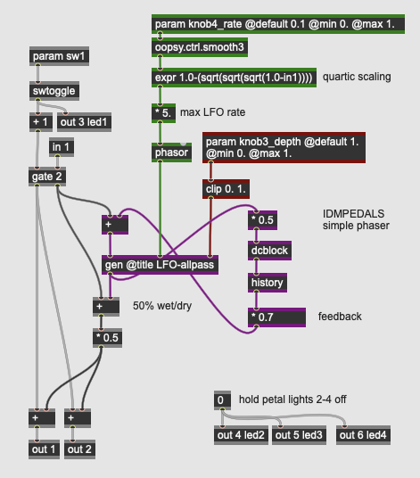
More Info...
A phaser is an electronic modulation effect that, uses phase cancellation to create peaks and troughs in the frequencies of an input signal. Like flanger and chorus effects, phaser effects typically use low fruquency oscillation to create the shifting effect; unlike flangers and chorus effects, the signal processing involved uses one or more allpass filters in lieu of longer delay lines. Electronic phasers simulate the sonic behavior of earlier, acoustic sound modelling devices such as the Leslie speaker.
Our simple phaser pedal, like our first chorus effect, has only two controls, knob3_depth and knob4_rate, which control, respectively, the depth (amplitude) and rate (frequency) of the LFO controlling the effect. Our LFO controls in the top-level patch consist of a sawtooth wave generated by the phasor operator which, along with the depth value from 0. to 1., goes into the LFO-allpass subpatch:
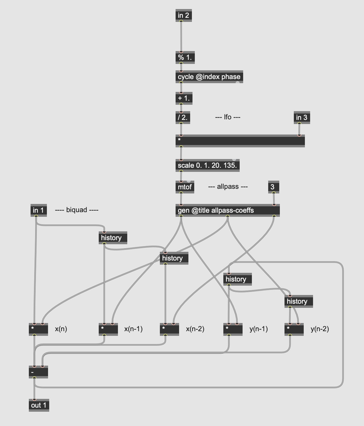
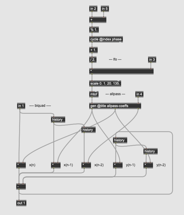
This subpatch contains the LFO itself (a cycle operator) which, when amplified by the depth parameter, is transformed (by the scale) operator into a sine wave sweeping a range of MIDI values. When converted back to frequency (by the mtof), they go into a subpatch that calculates the coefficients for the allpass filter:
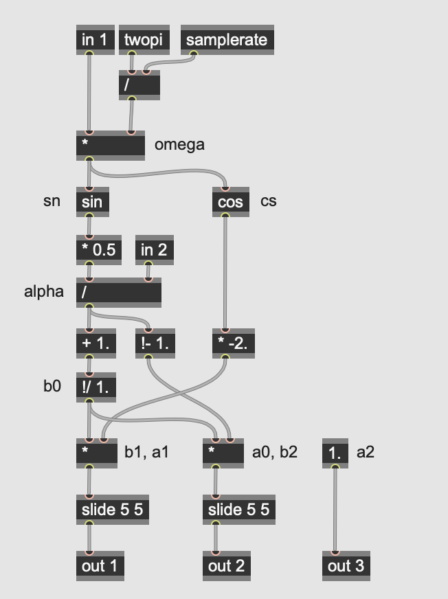
Our allpass filter uses the biquadratic filter equation with a variable center frequency and a fixed Q (sent from the parent patcher) and gain, solved as:
y[n] = ax[n] + bx[n-1] + cx[n-2] - dy[n-1] - ey[n-2]
where...
x = the input signal
y = the output signal
n = time (n is now, n-1 is one sample ago, etc.)
Fc = cutoff frequency
Q = 3.0 (quality factor)
SR = sampling rate

Ω = Fc * 2π/SR (sampling increment)
alpha = sin(Ω) * 0.5/Q

a = 1.0/(alpha+1.0)*(1.0-alpha)
b = 1.0/(alpha+1.0)*(-2.0*cos(Ω))
c = 1.0
d = b
e = a
These coefficients create a sweepable filter with no gain - in other words, the frequency content of the signal is unchanged (hence the term “allpass”). However, the phase relationships of the input signal are shifted by the filter. When combined with the dry signal (in the parent patch), the result is phase cancellation of different frequencies as the center frequency of the filter sweeps.
Finally, the phaser effect uses feedback to create a more resonant effect - the output of the allpass is multiplied by 0.7, delayed by one sample, and added back into the filter. This creates a more pronounced “whooshing” phasing effect, akin to classic phaser pedals.
Modulation: Multi-Stage Phaser
More Info...
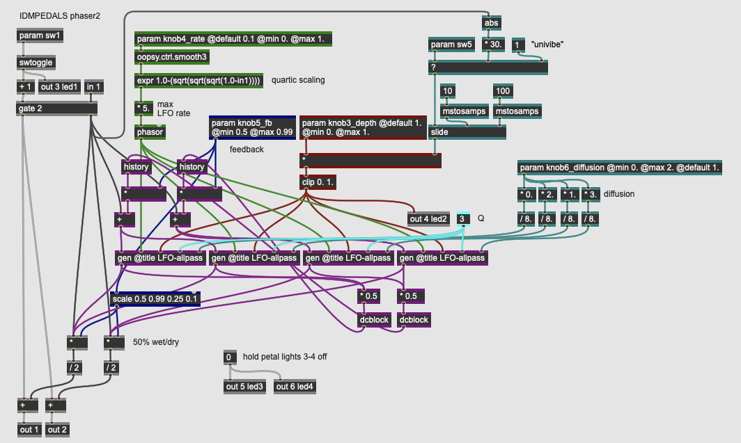
This pedal design implements a more complex phaser by using multiple stages of allpass filters to create more complex phasing effects. Like the previous pedal, it uses a single LFO for modulation; in this version, there are four identical allpass filters in parallel.
This pedal expands on the previous design with the addition of additional parameters. Our pedal has four continuous parameters and a switch:
- knob3_depth controls the depth (amplitude) of the modulating LFO, controlling the overall strength of the phase shifting effect.
- knob4_rate controls the rate (frequency) of the modulating LFO up to 5 Hz.
- knob5_fb controls the amount of feedback in the allpass network. Higher feedback will cause the phaser effect to become more resonant.
- knob6_diffusion controls the phase offset of the parallel allpass filters, controlling how out-of-phase they are to one another. The higher this value, the wider the phasing effect.
- sw5 engages an envelope follower on the input signal to scale the depth amount, so that louder input signals cause a deeper phaser effect. This simulates the behavior of classic amplitude-driven pedal circuits such as the Uni-Vibe.
The input signal and control parameters for the LFO go into the LFO-allpass subpatchers:
Like the previous pedal, this subpatch contains the LFO itself (a cycle operator) which, when amplified by the depth parameter, is transformed (by the scale) operator into a sine wave sweeping a range of MIDI values. When converted back to frequency (by the mtof), they go into a subpatch that calculates the coefficients for the allpass filter. Unlike the simple phaser example, this subpatch has additional inlets to allow for an independent Q factor for each filter (in 4) as well as a phase offset to the LFO (in 5, controlled by the output of knob6_diffusion).
As with the previous pedal, our allpass filter uses the biquadratic filter equation with a variable center frequency and a fixed Q (sent from the parent patcher) and gain, solved as:
y[n] = ax[n] + bx[n-1] + cx[n-2] - dy[n-1] - ey[n-2]
where...
x = the input signal
y = the output signal
n = time (n is now, n-1 is one sample ago, etc.)
Fc = cutoff frequency
Q = 3.0 (quality factor)
SR = sampling rate

Ω = Fc * 2π/SR (sampling increment)
alpha = sin(Ω) * 0.5/Q

a = 1.0/(alpha+1.0)*(1.0-alpha)
b = 1.0/(alpha+1.0)*(-2.0*cos(Ω))
c = 1.0
d = b
e = a
The output of our four allpass filters is then combined with the dry signal (in the parent patch), creating a complex network of phase cancellations across the frequency spectrum. When combined with feedback and implemented in stereo, this phaser can create a broad range of sounds.
Modulation: Harmonizer
More Info...
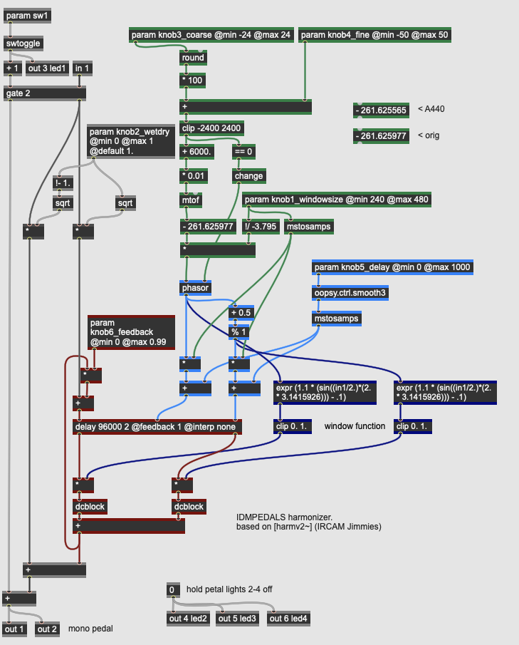
A harmonizer is a version of a pitch shifter effect that transposes the pitch of the input signal and (optionally) mixes it back in with the orginal. The pedal design here implements a time domain harmonizier / pitch shifter that works by leveraging the pitch shift effect caused by a moving delay line. When a delay line is modulated, a decreasing (long to short) delay time will result in the effective sampling rate of the signal to rise, causing the pitch of the signal to go up; when the delay time increases (short to long), the sampling rate drops, causing the pitch to go down. The challenge in this design is that, eventually, the delay line will run out of runway, so to speak, so the pitch shift cannot be maintained - the delay time will eventually reach zero or become so long as to cause the DSP to run out of memory. The solution used by most delay-based pitch shifters, then, is to use multiple delays; a consistent pitch shift can be accomplished by crossfading between the two delay lines which have out-of-phase modulating signals. When the first delay is audible, the second delay is resetting its delay time so that it can ramp again, and vice versa.
Harmonizers that are constructed using this algorithm have the added advantages of working within the context of a digital delay architecture: it doesn’t matter how far back in time the delay modulation that causes the pitch shift occurs; as a result, you can delay the harmony like an echo. Furthermore, you can use feedback to make the pitch shift cascade over and over. So in our pedal design, you can e.g. set the initial harmony to enter 250ms after the dry signal with a pitch shift of 1 semitones, and as the feedback is increased each repeat of the signal will rise an additional semitone.
Our harmonizer design has six parameters:
- knob1_windowsize is a parameter that sets how large a buffer of time the pitch shifting delay has to operate in; the larger this value, the less often the two delay taps have to crossfade, but the more noticeable it will be when it happens. A smaller window size creates a more granular sounding pitch shift, with a consistent artifact to the sound characteristic of these harmonizers.
- knob2_wetdry mixes between the dry input signal and the pitch shifted output of the effect; when set at 50%, the two signals are mixed evenly.
- knob3_coarse controls the amount of pitch shift the harmonizer applies to the input signal, in semitones. The pedal design allows for a pitch shift of +/- 24 semitones (2 octaves).
- knob4_fine controls the fine amount of pitch shift, in cents. The knob at the middle position applies no fine shifting, with a range of -50 / +50 cents (a quarter tone) in either direction.
- knob5_delay controls the base delay of the harmonizer effect, i.e. the amount of delay between the dry input signal and the pitch shifted signal. Up to one second (1000 milliseconds) of delay can be applied to the signal before the harmonized signal enters.
- knob6_feedback controls the amount of regeneration in the delay line. Increasing this value will create multiple (harmonized) echoes in the signal.
The logic in the gen~ patcher for calculating the specific speeds of phasor operators that are scrubbing the two taps of the delay operator are based on deriving the speed variation of the desired pitch. The two phasor operators are 180 degrees out of phase, so that one delay resets itself while the other is in the midst of its ramp. The expr operators on the lower right are synchronized ot the outputs of the *phasor signals and create window functions that procedurally crossfade the two delayed signals so that they overlap with minimal artifacts. The dcblock operators after the delay taps prevent dc bias from propagating through the signal.
The design of this particular harmonizer algorithm is adapted from the “jimmies”, a series of signal processing algorithms written by Zack Settel in 1993 for Max/FTS while at IRCAM, ported for Max/MSP by Richard Dudas in 1998.
Modulation: Sample-and-Hold Comb Filter
More Info...
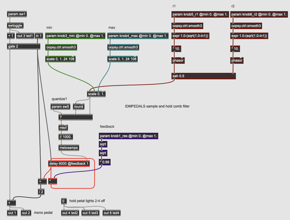
This pedal is a variation on a flanger effect where the resonant comb filter caused by the short delay line moves in discrete steps rather than smoothly. To accomplish this, two sawtooth waves are used as low frequency oscillators with their outputs patched into a sample and hold algorithm - when one sawtooth passes its midpoint, the secodn sawtooth’s value is sampled and held. The result is an arpeggio-style effect where the resonance of the flanger jumps around to different pitches. A switch allows these pitches to be quantized to a chromatic scale.
Our comb filter has five discrete parameters and a switch:
- knob1_res controls the overall resonance of the comb filter effect by controlling the feedback into the delay operator in the gen~ patcher.
- knob3_min and knob4_max set the minimum and maximum pitch boundaries of the comb effect by providing scaling parameters to the output of the sample and hold.
- knob5_r1 and knob6_r2 control the rates (frequencies) of two LFO phasor operators which input into the sah operator. The r2 sawtooth is the rate at which the sah operator will sample; the r1 sawtooth is the input being sampled. Both sawtooth generators can go up to 10 Hz. A slow r1 and a fast r2 will create a rising ladder effect; a fast r1 and a slow r2 will cause the comb frequency to jump around, or sometimes fall, as the rate of the oscillator to be sampled is faster than the rate of sampling (similar to a stroboscopic effect).
- sw5 causes the output of the scaled sample-and-hold (which is treated as a MIDI pitch) to be quantized by a round operator, fixing the comb filter pitches into a chromatic scale.
The actual comb filtering in the patch is accomplished by the delay operator, with its delay time calculated to be the wavelength of the desired frequency.
Modulation: Harmonic Filters
More Info...
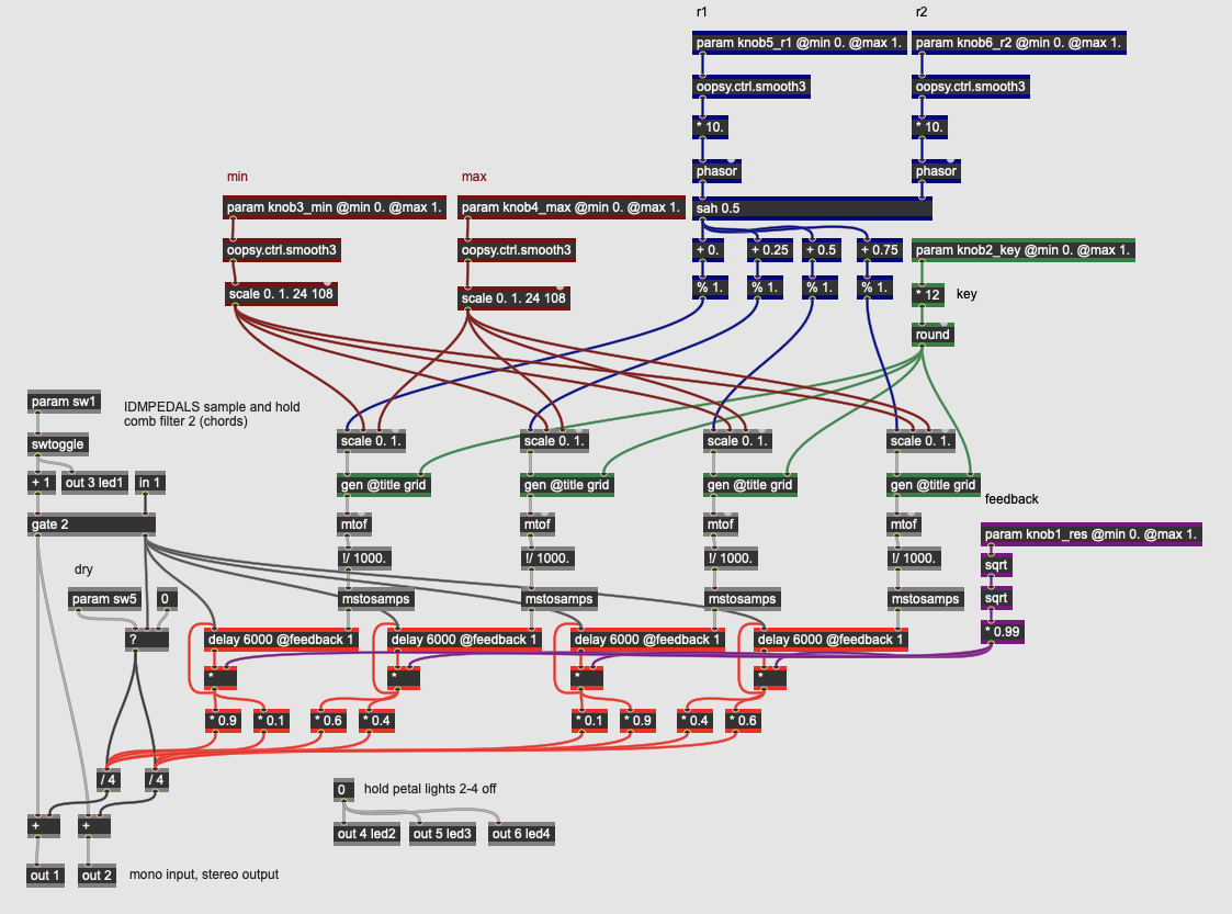
This pedal expands on the previous design by using four independent comb filters activated by a sample and hold algorithm. Unlike in the previous pedal design, these filters are intentionally put into a pitch grid of a major scale. This effect produces ringing chords as the filter resonances are tuned to harmonies within a scale.
This pedal has six continuous parameters:
- knob1_res controls the overall resonance of the comb filter effect by controlling the feedback into the delay operator in the gen~ patcher.
- knob2_key transposes the pitch grid for the harmonic filters through all 12 steps of the [chromatic scale], allowing us to select any (major) key for the resonation effect.
- knob3_min and knob4_max set the minimum and maximum pitch boundaries of the comb effect by providing scaling parameters to the output of the sample and hold.
- knob5_r1 and knob6_r2 control the rates (frequencies) of two LFO phasor operators which input into the sah operator. The r2 sawtooth is the rate at which the sah operator will sample; the r1 sawtooth is the input being sampled. Both sawtooth generators can go up to 10 Hz. A slow r1 and a fast r2 will create a rising ladder effect; a fast r1 and a slow r2 will cause the comb frequency to jump around, or sometimes fall, as the rate of the oscillator to be sampled is faster than the rate of sampling (similar to a stroboscopic effect).
The output of the sah operator in this algorithm is offset by 0.25, 0.5, and 0.75 (or 90, 180, and 270 degrees) so that each of the four filters are being activated by a different value. These four values are then input into a grid subpatcher:
This subpatch uses a codebox with GenExpr code to take a continuous MIDI value at in 1 and a key (or transposition) value at in 2 and output a quantized MIDI pitch in a major scale. It does this using the Data object in GenExpr, where a 12-point dataset maps a chromatic input to a diatonic output. The incoming MIDI value is separated into an octave and a pitch class, with the pitch class being indexed against the “ms” array stored in the Data object. The result is 7 out of 12 possible values being selected, creating harmonic resonances in a specific key.
Delay
Delay effects use a variety of techniques to time shift an input signal backwards in time, allowing the creation of echo and reverberation effects. Analog echo effects were accomplished originally using tape echo units and, later, bucket brigade devices, while reverberation was often accomplished artificially using spring tanks or metal plates. In DSP, digital delay lines, sometimes combined with digital filtering, are used for many of these effects.
Delay: Digital Delay
More Info...
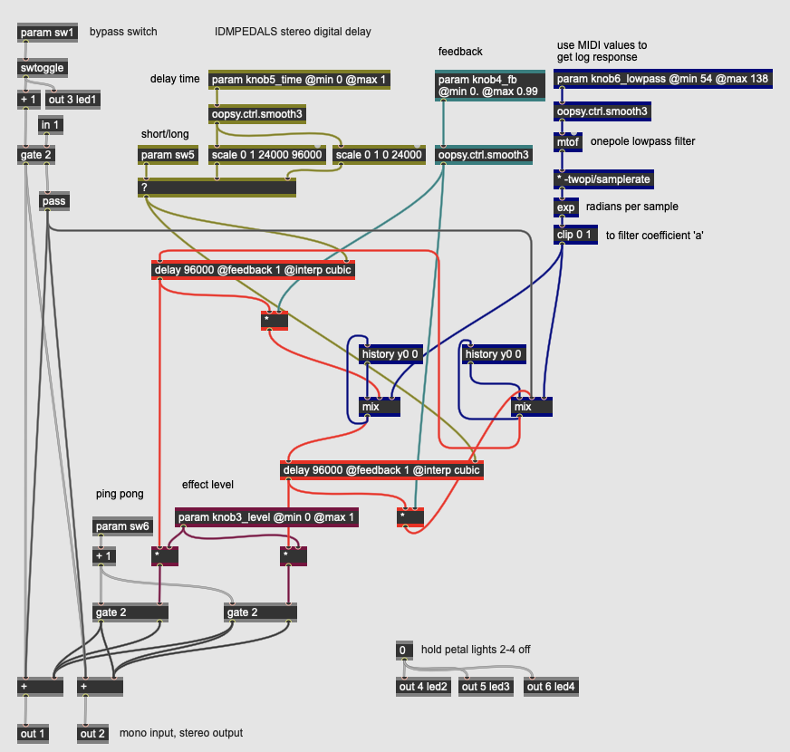
This pedal implements a simple, stereo digital delay with feedback and an inline lowpass filter. It uses two discrete delay lines so that a “ping-pong” effect can be enabled where subsequent echoes switch between the left and right outputs of a stereo field.
The pedal has four continuous parameters and two switches:
- knob3_level controls the overall level of the delay effect.
- knob4_fb controls the amount of regeneration (feedback) in the delay. Higher values will produce more echoes.
- knob5_time controls the delay time in the effect; depending on sw5, this control will sweep between 0-250 milliseconds and 250-1000 milliseconds of delay.
- knob6_lowpass controls the cutoff frequency of the one-pole lowpass filter in the feedback loop of the delay. A higher value will attenuate more of the frequency range. This filter equation is the same as used in the Lowpass Filter pedal, above.
- sw5 changes the scaling of knob5_time between short and long delays.
- sw6 engages a ping-pong effect at the stereo output of the pedal, routing the two delay operators to discrete outputs rather than mixing them.
By manipulating the controls, this digital delay pedal can do everything from automatic double tracking to long, regenerative echoes. The lowpass filter inline will progressively roll off high frequencies when engaged, creating an effect similar to analog delay units.
Delay: Multi-tap Delay
More Info...
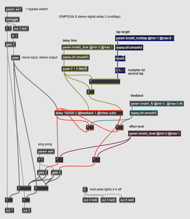
This pedal implements a multi-tap delay, where the digital delay signal is read from (or “tapped”) at multiple points, allowing for more than one delay time to be used concurrently with one delayed signal. When the different taps are in a temporal multiple of one another, multi-tap delays can be used to create rhythmic echo effects such as a dotted quarter note delay against a half note.
Our multi-tap delay implementation has four continuous parameters and one switch:
- knob3_level controls the overall level of the delay effect.
- knob4_fb controls the amount of regeneration (feedback) in the delay. Higher values will produce more echoes.
- knob5_time controls the delay time in the effect, up to 1000 milliseconds of delay.
- knob6_multitap determines the subdivision of knob5_time to be added to that time as the second tap, ensuring they are in a rhythmic ratio. The value ranges from 1 to 6. A value of 2, for example, will make the second tap 1.5 the duration of the first.
- sw5 engages a ping-pong effect at the stereo output of the pedal, routing the two delay taps to discrete outputs rather than mixing them.
Like in the previous pedal, the delay operator allocates the memory and sets up the digital delay line for the signal processing. The patch could easily be modified for more than two taps to create more complex echo effects.
Delay: Chowning Reverb
More Info...
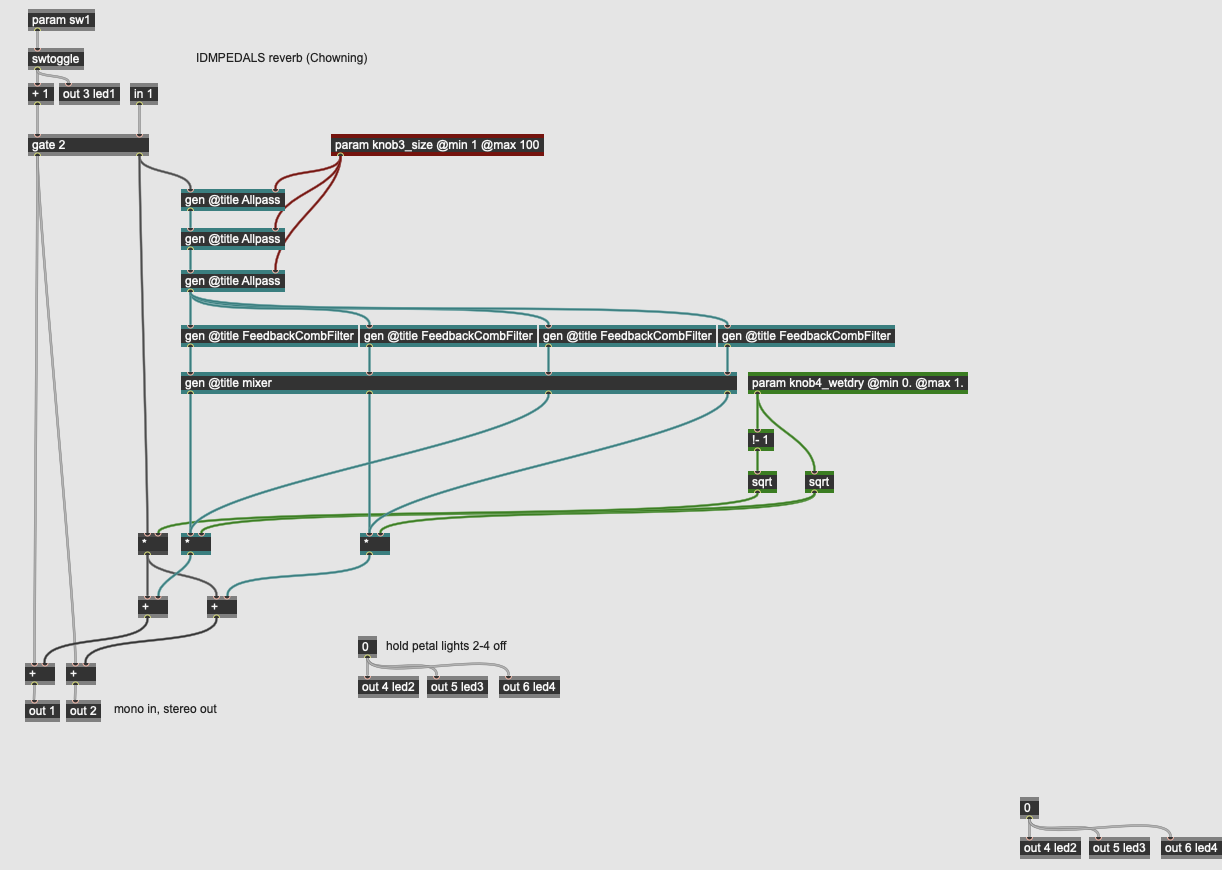
This pedal implements John Chowning’s reverberation algorithm, based on M. R. Schroeder’s theories for how to create artificial reverberation. The algorithm involves the sound passing through a network of three allpass filters in series, then four comb filters in parallel, before finally being mixed. The two parameters for the reverb are the size (knob3_size) which modifies the delay length of the allpass filters and the wet / dry mix (knob4_wetdry). The Chowning reverb algorithm has an excelelnt sound for its efficiency.
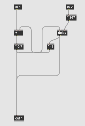
The allpass filters for the reverb consist of delay operators with varying length (the multiplier in each subpatch is different):
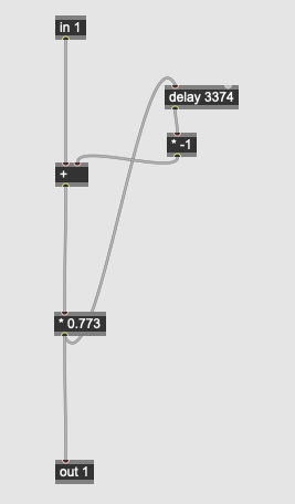
The delayed signal is inverted and mixed in with the original to create phase cancellations. The comb filters perform a similar effect with longer delays (again, each subpatch has slightly different coefficients):
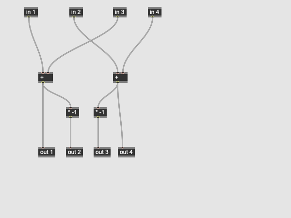
These comb filters create resonances akin to the walls of a physical space. Finally, the comb network is mixed together in a mixer subpatch:
The outputs of the mixer are crosspatched to create a stereo image by combining in and out of phase copies of the comb filter outputs in the left and right channels. The result is a nice sounding reverberator that uses an economical amount of signal processing to get the job done.
Delay: Freeverb
More Info...
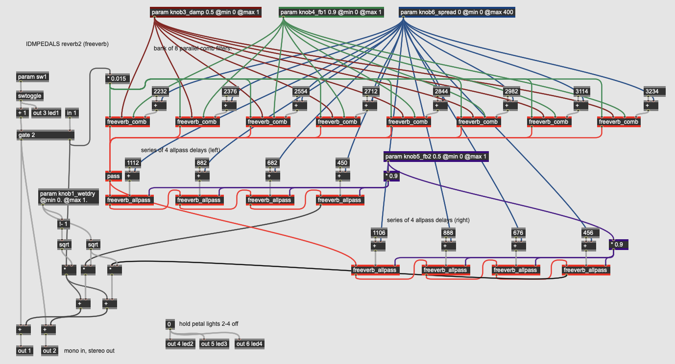
This pedal implements Freeverb, an open-source reverberation algorithm written by “Jezar at Dreampoint” and widely used in free digital reverbs. The algorithm uses a network of eight parallel comb filters sent into a stereo network of four series allpass filters on either side. Unlike the Chowning reverberator, the Freeverb algorithm incorporates parameters for damping (knob3_damp) with a one-pole lowpass filter inside each comb filter’s feedback stage, as well as two parameters for feedback (knob4_fb and knob5_fb2) which control the amount of regeneration in the comb and allpass filters, respectively. A fourth parameter, knob6_spread, spaces out the allpass delays to create a “larger” room as well as a broader stereo field. Finally, knob1_wetdry contorls the mix between the input signal and the reverberation.
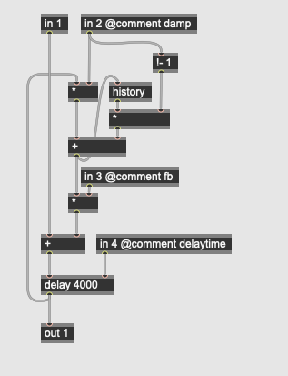
The comb filters use the delay operator with different values for each instance of the subpatch in the effect, as well as a simple lowpass filter (the history operator mixed in with the input signal):
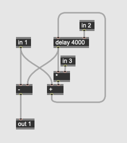
The comb filter also has an inlet for feedback. The allpass filter is similar, with each subpatch having a different value which the reverb’s spread parameter multiplies:
The Freeverb algorithm is a bit more complex than the Chowning, but it allows for more parametric experimentation and can create long, sustained reverb tails reminiscent of highly reverberant, large spaces.
Delay: Creepy Reverb
More Info...
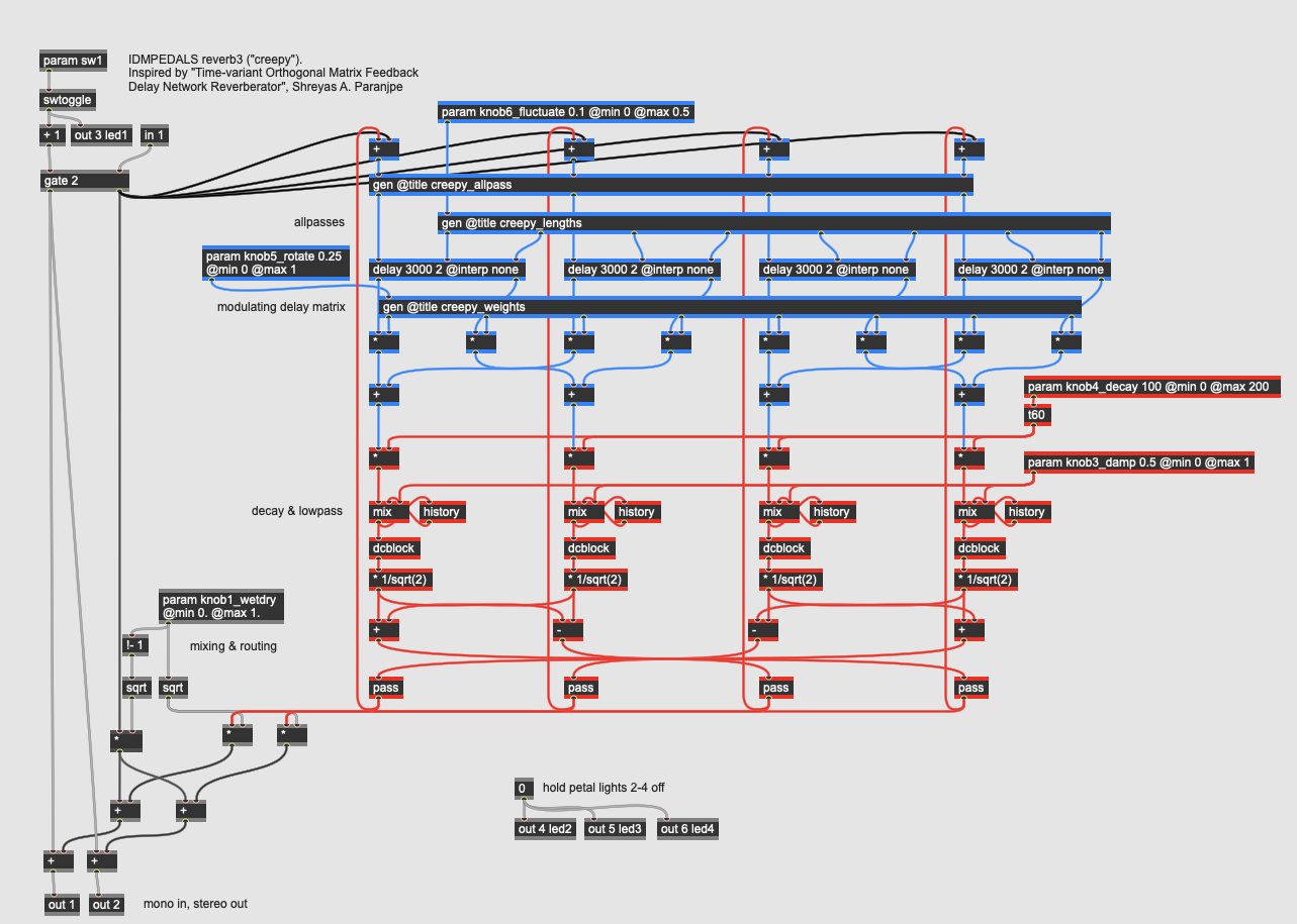
This reverb implements Shreyas A. Paranjpe’s reverberation algorithm that uses a matrix of delay taps to create a very dense reverb with an efficient amount of delay memory. Additionally, this reverberator allows for modulation-like effects within the reverb that allow for some very “creepy” sounds (hence the name). This patch is adapted from the gen~ example of the same name in Max/MSP.
The reverb pedal has five parameters:
- knob1_wetdry controls the mix between the reverberation and the dry signal.
- knob3_damp controls the dampening on the reverb using a 1-pole lowpass filter at the output of the comb filters, implemented through mix and history operators.
- knob4_decay controls the decay time (amount of regeneration) in the reverberation. This maps to the overall size of the virtual space.
- knob5_rotate controls the speed of an LFO controlling rotatation of the mixing matrix. This value causes the reverberation to change its character over time.
- knob6_fluctuate controls the overall delay matrix, changing the character of the space.
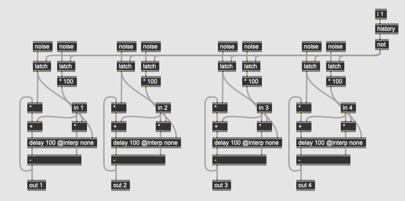
The three gen~ subpatchers for the reverb algorithm configure the allpass filter block, longer delays for the comb filters, and the mixer block for the various weights. Random values are used (entered from noise operators through the latch operator) to set the delay times and gains for the filters at the outset, so that each instance of the reverb sounds slightly different.
Special FX
Special effects pedals include algorithms outside of the traditional categories: these include effects that integrate synthesis in the signal chain, effects that generate non-musical characteristics, and algorithms that behave idiosynchronously by design.
Special FX: Subharmonic Oscillator
More Info...
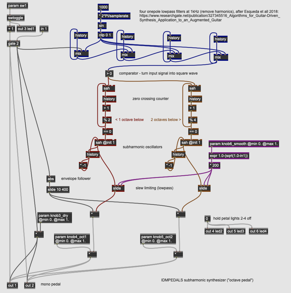
This pedal implements an octave effect on the input signal, where a synthesized tone tracks both the amplitude and frequency of a monophonic input, generating tones one and two octaves below the fundamental of the original signal. Pitch tracking of the input signal is accomplished by a series of steps. First, the input signal is filtered so that frequencies above 1kHz are attenuated using four one-pole lowpass filters in series. The filtered input signal is then run through a comparator (a > operator) to turn the input into a square wave. This square wave then serves as a digital trigger for two sample-and-hold (sah) operators which, combined with the history operators, simulate a phase-locked loop to generate two new square waves. These square waves have a base frequency that is exactly 1/2 and 1/4 (one and two octaves below) the input signal.
These control signals then drive two additional sah operators that serve as full-range subharmonic oscillators. The slide operator then smooths these signals based on the knob6_smooth parameter, rounding off the signal to make it closer to a triangle wave. These signals are then multiplied by the output of an envelope follower tracking the amplitude of the input signal. These final, synthesized tones can then be mixed together with the dry input using knob3_dry, knob4_oct1, and knob5_oct2.
Octave pedals work best with clean, monophonic inputs and are an early case of simple, instrument-controlled synthesizers.
Special FX: SHSine
More Info...
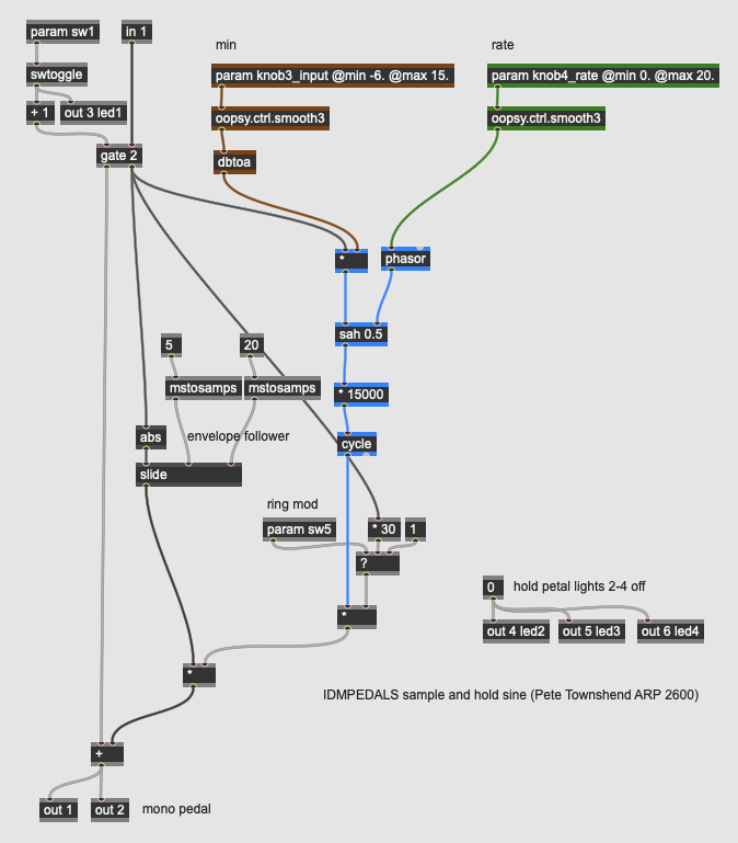
This pedal implements a technique used by Pete Townshend on the ARP2600 synthesizer in the 1970s, where he would use the amplitude of his guitar (via the ARP’s envelope follower) to control the frequency of a sine wave. The louder he played, the higher the sine wave’s frequency. The rate at which the sine wave updates its frequency is controlled by a sample-and-hold circuit where the trigger speed is determined by the knob4_rate parameter. The knob3_input parameter controls the scaling level of the input signal, and sw5 multiplies the sine with the raw input signal, creating a ring modulation effect (see below).
Musicians regularly used the built-in envelope follower of the ARP 2600 in creative ways, as it could be patched into any control source on the synthesizer. Having the amplitude of an instrument control the frequency of a synthesizer is an unorthodox technique that can create some very cool sounds.
Special FX: Ring Modulator
More Info...
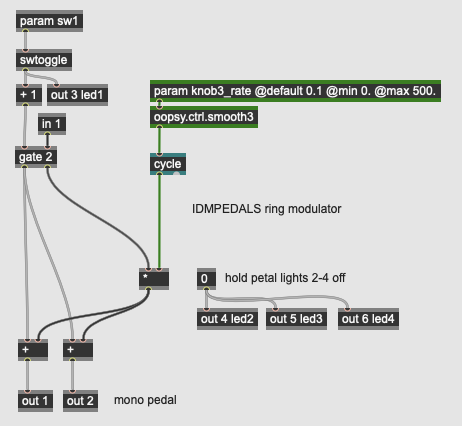
A ring modulator is a very early modulation technique where a carrier signal is multiplied by a modulating signal (normally a fixed oscillator). The output is the sum and differences of the two sources frequency content; this allows for easily creating unpitched, inharmonic, robotic, or metallic sounds from harmonic instruments. In analog circuitry, ring modulation is accomplished using a network of diodes in a loop, or ring-style arrangement. Using DSP, ring modulation can be accomplished using a simple signal multiplication - the * operator in gen~ does the trick.
Our ring modulator pedal has one parameter - the frequency of the modulating oscillator set by knob3_rate. The input signal is then multiplied with this oscillator (a sine wave generated by the cycle operator). Low frequencies will sound like a tremolo effect - as the frequencies raise above 20Hz, the sideband frequencies of the ring modulation become audible.
Special FX: Frequency Shifter
More Info...
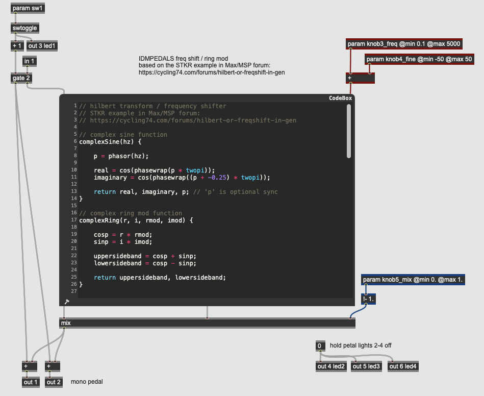
A frequency shifter adds and subtracts a fixed frequency to an input signal - this technique differs from pitch shifting in that the process creates inharmonic outputs - adding to rather than multiplying the frequency content of a signal will easily disrupt the harmonic ratios between partials. Like ring modulation, frequency shifting easily creates metallic or robotic sound effects from instrument inputs; unlike ring modulation, the upper and lower sideband frequencies can be independently mixed.
This pedal uses three continuous parameters and one switch:
- knob3_freq controls the course frequency of the modulating oscillator - this frequency will be added and subtracted to the harmonic content of the input.
- knob4_fine allows you to fine tun the modulating oscillator’s frequency.
- knob5_mix blends between the lower (carrier input - modulator frequency) and upper (carrier input + modulator frequency) outputs of the effect.
- sw5 changes the mode of calculation for the frequency shifting.
Our effect uses GenExpr code posted on the Max/MSP forum, and offers two techniques for frequency shifting: one technique implements a hilbert transform and the other a complex IIR filter.
// hilbert transform / frequency shifter
// STKR example in Max/MSP forum:
// https://cycling74.com/forums/hilbert-or-freqshift-in-gen

// complex sine function
complexSine(hz) {

	p = phasor(hz);

	real = cos(phasewrap(p * twopi));
	imaginary = cos(phasewrap((p + -0.25) * twopi));

	return real, imaginary, p; // 'p' is optional sync
}

// complex ring mod function
complexRing(r, i, rmod, imod) {

	cosp = r * rmod;
	sinp = i * imod;

	uppersideband = cosp + sinp;
	lowersideband = cosp - sinp;

	return uppersideband, lowersideband;
}

// two-pole, two-zero biquad filter (transposed direct form 2)
biquadTdf2(x, a0, a1, a2, b1, b2) {

	History x1(0), x2(0);

	y = (x * a0) + x2;
	x2 = ((x * a1) - (y * b1)) + x1;
	x1 = (x * a2) - (y * b2);

	return y;
}

// hilbert quadrature filter
hilbertBiquad(x0) {

	x1 = biquadTdf2(x0, 0.94657, -1.94632, 1., -1.94632, 0.94657);
	x2 = biquadTdf2(x1, 0.06338, -0.83774, 1., -0.83774, 0.06338);

	y1 = biquadTdf2(x0, -0.260502, 0.02569, 1., 0.02569, -0.260502);
	y2 = biquadTdf2(y1, 0.870686, -1.8685, 1., -1.8685, 0.870686);

	return x2, y2; // real, imaginary
}

// polyphase IIR filter
polyphaseIIR(y0) {
	// one sample delay
	History x0(0);
	// first phase allpass cascade
	x1 = biquadTdf2(x0, 0.479401,	0., -1., 0.,	-0.479401);
	x2 = biquadTdf2(x1, 0.876218,	0., -1., 0.,	-0.876218);
	x3 = biquadTdf2(x2, 0.976599,	0., -1., 0.,	-0.976599);
	x4 = biquadTdf2(x3, 0.9975,		0., -1., 0.,	-0.9975);
	// second phase allpass cascade
	y1 = biquadTdf2(y0, 0.161758,	0., -1., 0.,	-0.161758);
	y2 = biquadTdf2(y1, 0.733029,	0., -1., 0.,	-0.733029);
	y3 = biquadTdf2(y2, 0.94535,	0., -1., 0.,	-0.94535);
	y4 = biquadTdf2(y3, 0.990598,	0., -1., 0.,	-0.990598);
	// update
	x0 = y0;
	// real, imaginary
	return x4, y4;
}

// Param sw5 = use 4-pole hilbert or 8-pole polyphase IIR
Param sw5(0, min=0, max=1);
md = int(sw5); // mode
x = in1;						 // audio in

r, i = hilbertBiquad(x); // 0, hilbert = default
if (md == 1) r, i = polyphaseIIR(x); // 1, polyphase IIR

rm, ri, sync = complexSine(in2); // modulating frequency (Hz)

out1, out2 = complexRing(r, i, rm, ri);
out3 = sync;
This pedal can be used to create a variety of special effects with an instrument signal.
