Blinking Beeping Moving Sensing
Class page for IDM NYU DM-UY 4913 J Fall 2024
Syllabus Weekly Schedule Assignments & Projects Resources Cheat Sheet
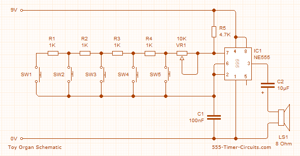
555 Timer Monophonic Organ
Using a 555 chip, you’re going to build an organ that will produce a different tone based off the button that is pressed.
The 555 is set up as an astable vibrator - its output changes frequency determined by the resistors and capacitors connected to pins 2, 6, and 7. Because the resistrs are set up in series as a ladder, each has a different amount of resistance in total even if they have the same value. The voltage going into the chip dtrmines how quickly the capacitor discharges changing the frequency of the sound. The higher the resistance, the lower the frequency.

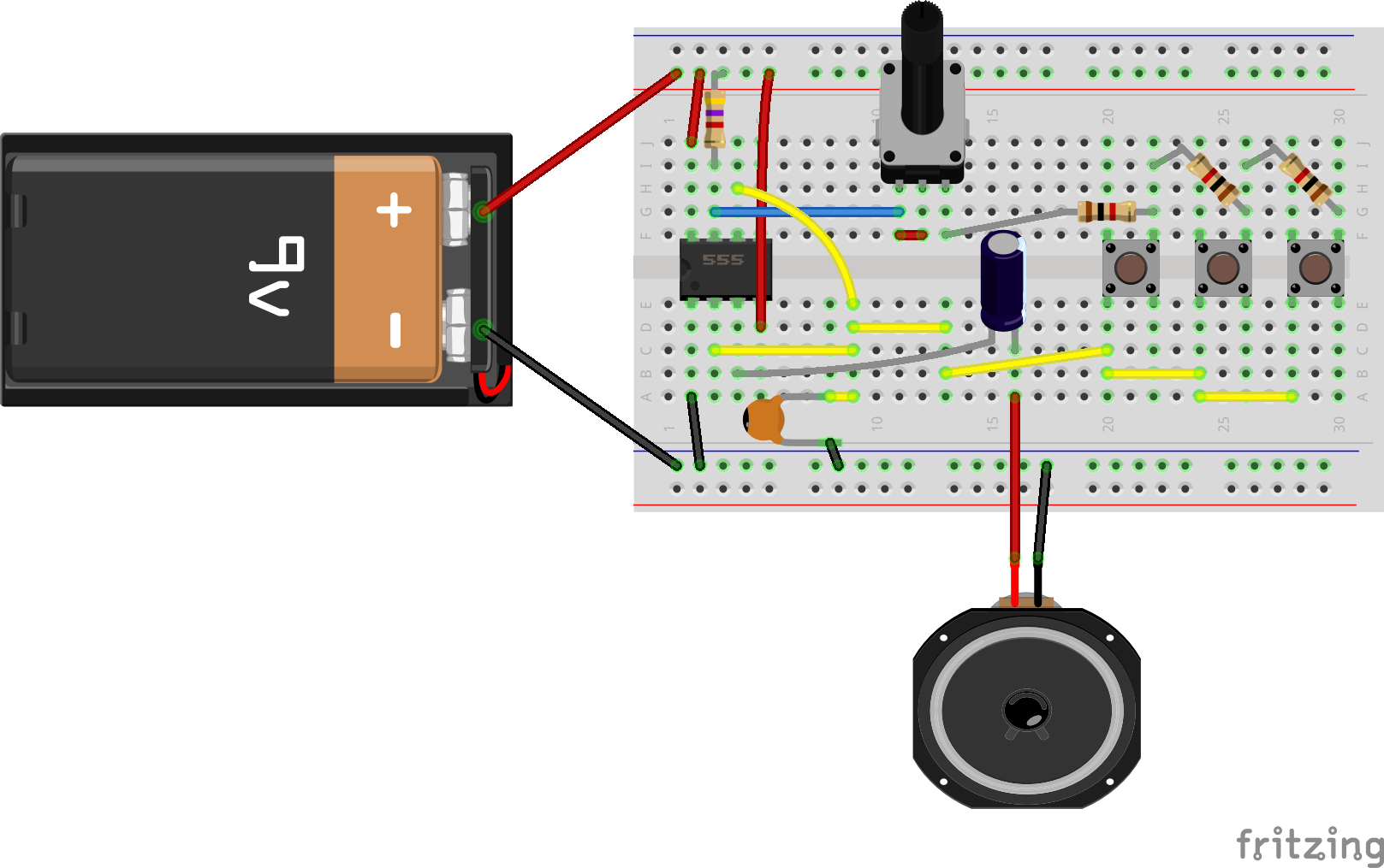
The finished product

Step 1 - the Breadboard

Step 2 - the IC
Place the IC in the board with the dot facing the closest edge of the board

Step 3 - power and ground
Connect pin 1 to ground and pin 8 to power

Step 4 - finish the chip wiring
Connect pin 7 to power throigh a 4.7k ohm resistor, and connect pin 4 to power

Step 5 - pull out a lead for a pot
bring a wire out from pin 7

Step 6 - wire the pot
add a 100k pot so one end connects to pin 7. bridge the center pin and the terminal connected to pin 7

Step 7 - add some switches
Add your switches to the far end of the bb

Step 8 - make a resistor ladder
Add 1.1k rersistors in series with each other connected to one terminal of the pot, ending with the termonal of one of the switches. Each resistor shpuld connect to two switches

Step 9 - connnect pins 2 and 6 to the switches
connect pins 2 and 6 to the switches in parallel

Step 10 - add the capacitors
Connect a small ceramic cap (labeled 104) to ground and the junction of pins 2, 6, and the switches. Connect a polarized 100uf capacitor to the circuit with the anode (long leg) connected to pin 3 of the 555 and the other pin in an otherwise empty column

Step 10 - add the speaker!
Connect one end of the speaker to the pin with the polarized capacitor, and the other end to ground

Step 11 - add the power and press play!
Connect your battery to the bus rows and make some noise
