Blinking Beeping Moving Sensing
Class page for IDM NYU DM-UY 4913 J Fall 2024
Syllabus Weekly Schedule Assignments & Projects Resources Cheat Sheet
Notes on Digital Input and Output
While you’ve successfully managed to turn some lights on, you’ve so far been limited in that you have only been able to do one thing at a time. With software, we can do multiple things (or at least have the appearance of multiple things) happening. We can also control things so that they happen automagically. It’s the interaction of algorithims, memory, and whatever input you provide that make the magic happen. Through software, we can reconfigure a machine to do anything we darn well please, including teaching the machine to behave like a different machine (see also, emulators).
There a many many different types of software languages. Sadly, the ones that I think are most interesting are the least useful to us. Generally speaking though, languages can be laid out along a continuum of “high-level” to “low-level”. As we’re not planning on talking directly to the silicon in the chips we’re using, we can use a higher level language that is closer to natural human language than natural machine language.
The general idea behind software is that it abstracts machine instructions (a series of 0s and 1s) and gives us something closer to what we might use to communicate with one another. We have limited options for the Arduino. The Arduino language is a high level variant of C with a few C++ features. These are different than python or javascript in a number of ways, most importantly in that they are ‘typed’. Some microcontrollers do allow you to write python, lua, or javascript for them- but that’s living on the edge, we won’t visit that in class.
While you can write software anywhere, a scrap of paper, text pad, back of your hand, it’s best to write it in an application that will compile the code into something meaningful to the machine. With Arduino, the makers of the hardware have created an IDE (Integrated Development Environment) that allows us to write code and compile it to machine language in one place. It will also do a nifty backflip and load the code onto the microcontroller for us. Once on the microcontroller, the code will operate independently from the IDE. You can upload your code, unplug the microcontroller from your computer, and let it go on its own merry way.
Read this to get a good idea of the ins and outs of the Arduino IDE for your desktop. It’s also possible to use a cloud based IDE, a commandline based IDE, or an older version. We’re going to use the 2.x branch in this course.
Thanks to it’s open hardware philosophy (like open source software, but for physical objects) there are as many Arduino clones as there are stars in the sky. This has also cemented its place in the media art world as the cornerstone around which physical things are made. There are a bunch of variants (Uno, MKR1000, Micro, Due, Zero, Lilypad, Gemma, Ethernet, etc etc), each with a particular specialty.
An Arduino can do a bunch of things, but what it really excels at is gathering information about the physical world through inputs, doing a little processing on the values it reads off those inputs, and spitting back information about that reading. This information can take the form of a motor spinning, a buzzer buzzing, sending data to a multimedia computer for more processing, or lighting up an LED. This last one is the easiest, so we’ll start there.
I like to divide up the tasks individually when working with software and hardware. I find this makes the task of debugging (which will become your frenemy by the end of this course) much easier. Let’s start with the code.
When you first open the Arduino IDE, you get a blank window that has some funny looking writing inside of it.
That’s code! Specifically it’s a pair of function declarations and comments.
Functions are the parts of code that actually do stuff. Below is the function declaration for setup().
void setup() {
  // put your setup code here, to run once:

}
void is what the function will return. Some functions will respond with a number, object or character when called. This one doesn’t return anything, so it’s “void” (not related to the existential dread you get when faced with a blank window when coding).
setup is the name of the function. setup is a special function in Arduino language in that it is needed for every program, and will only run once when the program first runs (after a reset, power on, or new program upload). The () is where you would add any arguments that the function requires to run. setup needs none, and can be left empty.
The curly brackets (aka braces) {} are used to remark the start and end of what the function is supposed to do. You would write all your code for setup() between these. If a function is a paragraph of text, these mark its contents.
// indicates a single line comment. This is something the IDE’s compiler will ignore. Comments are the most helpful thing you will ever use when programming. They are great for reviewing what you were doing 6 months earlier when you first wrote the program. You can write comments over several lines of by encapsulating them with /* ….. */ as seen below :
void setup() {
  /* This is a multi-line comment.
  Everything between the paired asterisk
  and slash is ignored by the computer */
}
After setup(), you call the function loop().
void loop() {
  // put your main code here, to run repeatedly:

}
loop() runs over and over again forever until the power goes out or you press the reset button or upload a new sketch. The speed at which it goes through your code depends on what you’re doing. Generally it moves through these lines faster than you think.
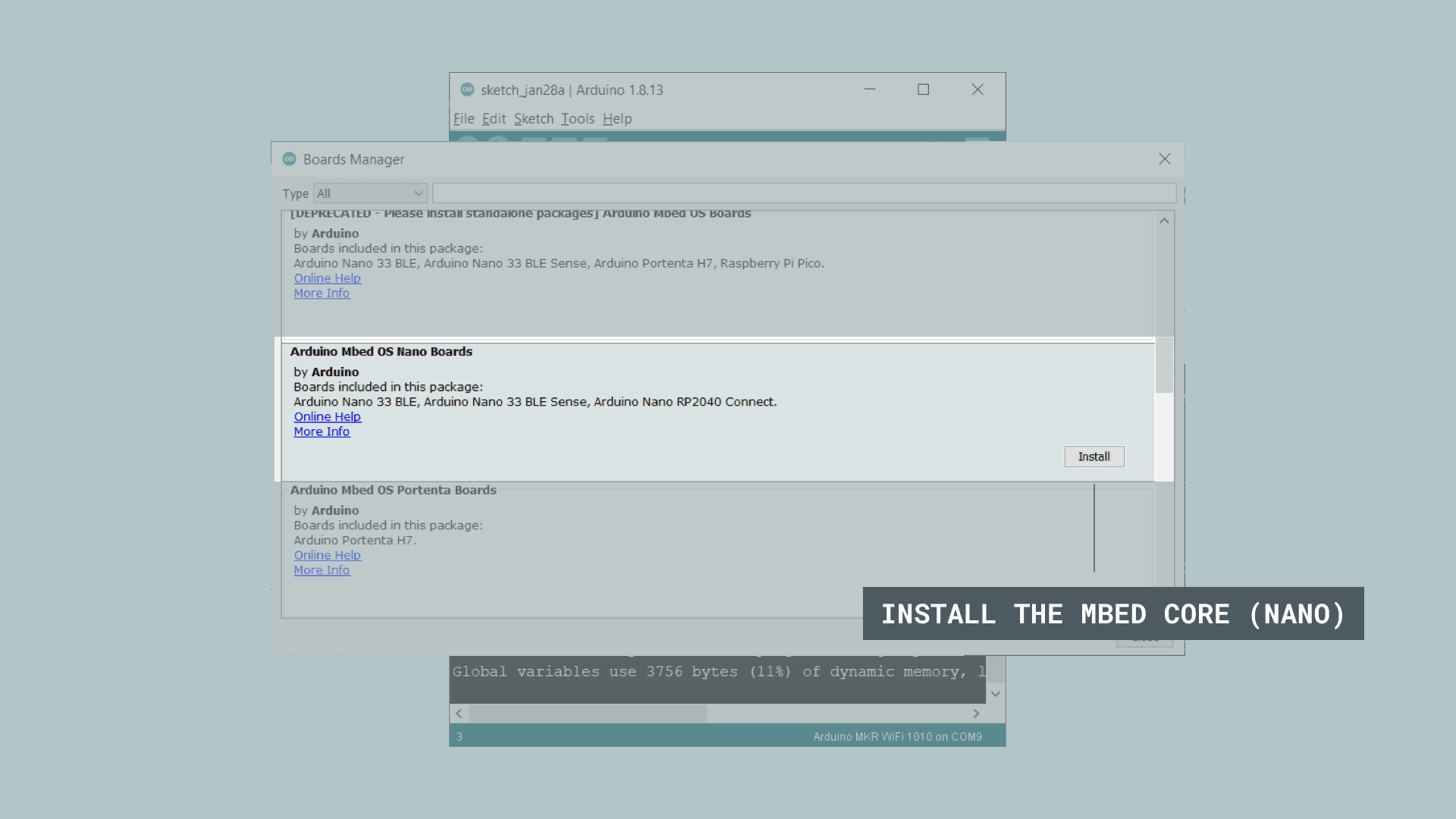
Before we do the “Hello World” of hardware and get an LED to blink, we need to install the board definitions for the Nano BLE 33. In the IDE, select the Tools > Boards > Boards Manager. Search for ‘Arduino Mbed OS Nano Boards’ and press the Install button. Once it has installed, you can close the board manager.
In setup(), you need to declare what pin you want to turn into an output. The pinMode() function takes care of this for us. pinMode() takes 2 arguments, the first is the number of the pin we want to set, and the second is what kind of pin we want it to be (INPUT or OUTPUT). In this example, we’ll make pin 2 an OUTPUT.
void setup() {
  // put your setup code here, to run once:
  pinMode(2, OUTPUT);
}
That semicolon (;) you see at the end is going to bedevil you for a long time. Think of it like a period at the end of a sentence. While humans can be pretty forgiving of run on sentences even when they lack full punctuation we can typically suss out the meaning of the author’s intent. Computers are not so forgiving, and need a semicolon after each line of code.
In loop(), you want to set the voltage of the pin to turn the LED on and off. digitalWrite() allows us to do this by telling a particular pin wether it is HIGH (in which case it turn the pin “on” and putting out 5V) or LOW (“off”, or 0V). We’ll want to alternate between on and off to make the blinking happen.
void loop() { // put your main code here, to run repeatedly:
  digitalWrite(2, HIGH);
  delay(1000);
  digitalWrite(2, LOW);
  delay(1000);
}
The delay() function makes your program pause. delay() can be helpful, but it will freeze the micrcontroller’s state. This means nothing else while delay() is ticking down. You can change the duration of how long it stops as an argument. This value is in milliseconds because computers run crazy fast. This will loop forever and ever and ever.
Let’s build a circuit! It’s very similar to the one you made last week.
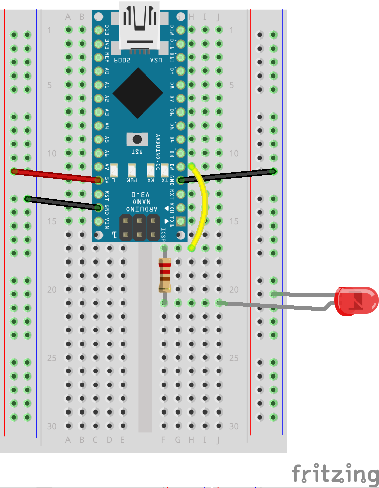
Connect the anode (longer leg) of the LED to pin 2. Connect the cathode (short leg) to ground through a resistor (between 220ohm – 1kilohm is fine). Plug the Arduino into your computer and get ready to upload the code.
You need to select which board you’re using in the “Tools” menu, and the port the board is connected to. This insures the IDE prepares the code for the right kind of board, and tries to communicate on the proper port.
Hooray! you should see some lights on the board flash, then the LED will start to blink!
Now let’s try and get some input. We’ll start with the code again.
void setup() {
  pinMode(2,OUTPUT);
  pinMode(3,INPUT);
}
Here, we’re adding pin 3 as an INPUT. The Arduino can now read the voltage on the pin and let us know if it is HIGH or LOW.
Now on to the loop() where there’s some more new things you may recognize :
void loop() {
  if (digitalRead(3) == HIGH) {
    digitalWrite(2, HIGH);
    delay(1000);
    digitalWrite(2, LOW);
    delay(1000);
  } else {
    digitalWrite(2, LOW);
  }
}
This introduces a number of new ideas in one pass. Let’s start with something you’re already familiar-ish with. digitalRead() is a function that will check the voltage of the pin you provide as an argument. digitalRead() returns a value, either HIGH or LOW, depending on the state of the pin. If there is 5V on the pin, it will give us HIGH, 0V will give us LOW.
We want the LED to blink when the button is pressed, that is, the voltage on the pin is HIGH. We can test this condition with an if() statement. if() evaluates a statement to see if it is true or false. If the condition is met (true) it will execute the code in the curly brackets that follow it. If not, it will ignore that code.
Note that we’re a double == in the if() statement. This is very different than a single =. This is one of those lovely aspects of programming that is going to cause you more headaches moving forward. Sorry about that. The == is a comparison. A single = sets a value (which we will address soon enough).
We can read the code above like this : “Read the value of pin 3, if there’s 5V there, blink the LED… “. The else is an aspect of the if() statement that helps control the flow of your program a bit better. It’s not necessary in this instance, but it’s not the worst thing to include either. All it’s doing here is adding an addendum to the above : “Read the value of pin 3, if it is HIGH, blink the LED. Else, if the value is LOW, don’t turn the LED on at all”.
Now that we have the code, let’s adjust our circuit by adding a switch. This is not as straightforward as you want it to be either.
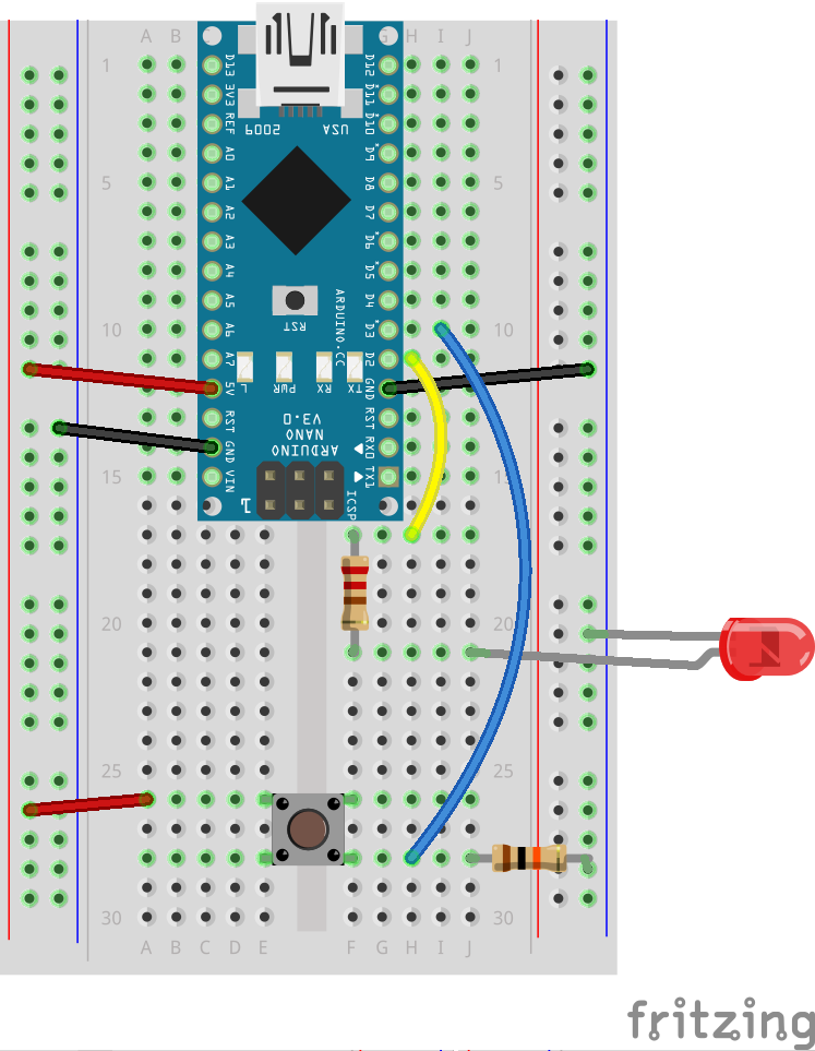
You’re probably asking what the heck that 10kilohm resistor is doing in there.
When you press the button as wired above, 5V flows across the resistor. If it was a smaller value, it would get hot as it’s the only load in the circuit. When the button is not pressed, it provides a reference to ground. Without that reference, the pin would be “floating” and may pick up all sorts of stray electricity. This 10k resistor is your insurance that you will always get the proper reading from the switch.
Now that you’ve mastered the basics of writing code for digital input and output, get the Arduino to do multiple things at once. Flash a light when one button is pressed, flash another when it’s released. Get some lights to alternate their rhythm. Make a career out of flashing lights on and off.
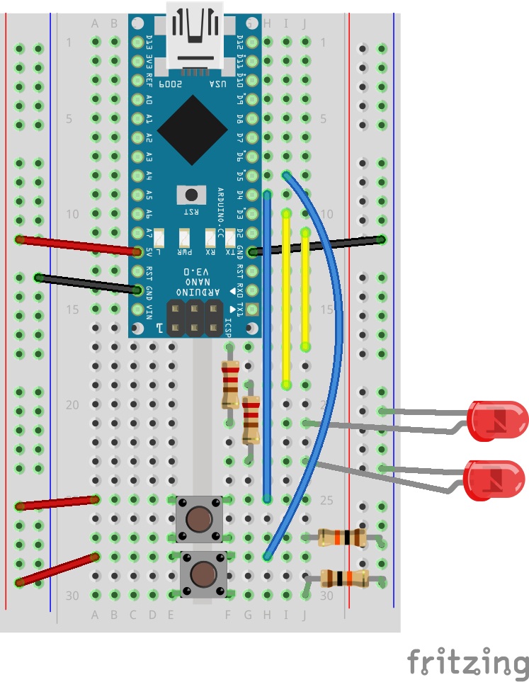
Here are the 2 additional circuits :
2 LEDs, 1 switch
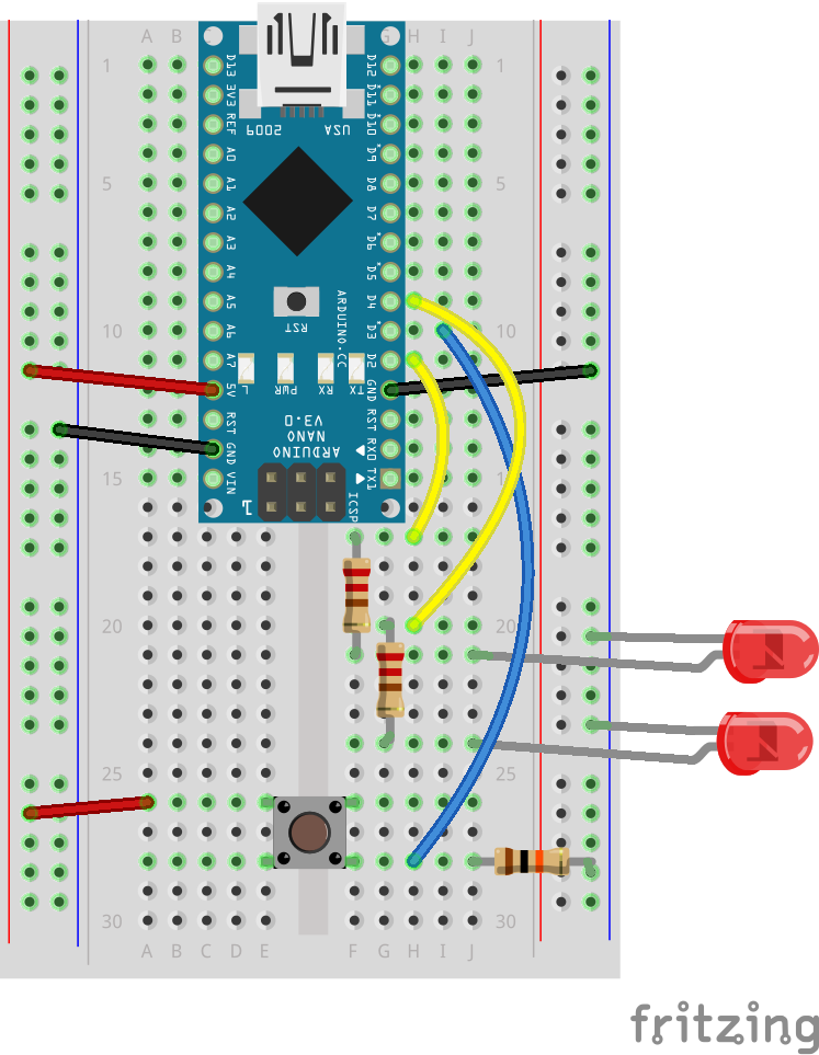
2 LEDs, 2 switches (for use with the and/or program)