Blinking Beeping Moving Sensing
Class page for IDM NYU DM-UY 4913 J Fall 2024
Syllabus Weekly Schedule Assignments & Projects Resources Cheat Sheet
This far, we’ve worked with digital sensors, that is, things that are either on or off. While this binary system is great for computers, we live in a world that’s not quite so black and white.
The physical world exists along a spectrum, and fortunately for us, there are a wide variety of sensors that can get information about the physical world. With some sleight of hand, we can teach computers about the world around us. We’ll address a few of the many different types of sensors in a little bit. First, how do we trick the computer?
On your Arduino, there’s a special circuit called an ADC (an analog to digital converter). This samples the voltage on the analog input pins (A0-A5 on an Uno, A0-A7 on your Nano BLE 33) allowing us to translate voltage into a numeric representation. Different microcontrollers have different sampling resolutions. The Arduinos we are using have a 10-bit resolution. This means we can get a value between 0-1023 that represents the analog voltage on the pin (1024 total steps). 0 corresponds to 0 volts, 1023 corresponds to 3.3v (or 5V), and everything else maps neatly in between (512 is 1.68V(or 2.5V), 768 is 2.5V (or 3.66V), etc). An int is the ideal data to to store this in.
To read the voltage on an analog pin, call analogRead(). This takes one argument, the pin you wish to read the value from.
mySensorValue=analogRead(A0);
We can see the results of an analogRead in number of ways. To replicate what we’ve been doing with the LEDs so far, we can use this value to change the delay of our blinking light :
const int ledPin=2;// naming the ledPin. constants don't change
const int potPin=A0;// naming the input pin
int sensorVal;// holds the sensor value, also delays the blinking LED

void setup(){
    pinMode(ledPin,OUTPUT);// set the LED pin as an output
}

void loop(){
    int delayTime;// local variable to hold delay time
    sensorVal=analogRead(potPin);// read the sensor value, save it in a variable
    delayTime=sensorVal;// save the value in the local var
    digitalWrite(ledPin,HIGH);
    delay(delayTime);// delay per sensor reading
    digitalWrite(ledPin,LOW);
    delay(delayTime);// delay per sensor reading
}
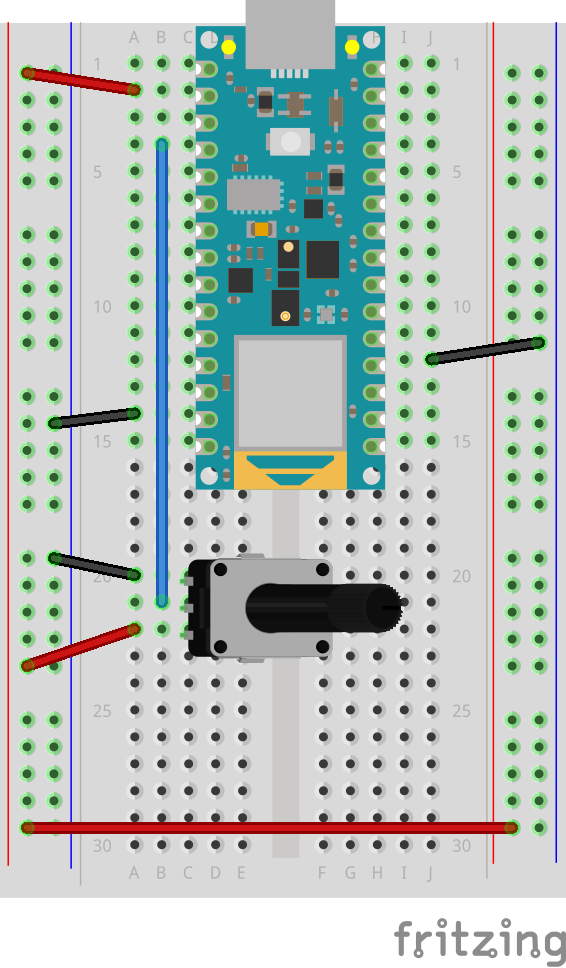
Now that we have our code, let’s look at the circuit. The LED on pin 2 should be familiar from earlier week. Our sensor will be connected to pin A0. The easiest thing to get started with is a potentiometer.
A potentiometer is a self contained voltage divider, often appearing as a knob or slider. The inside of a pot looks like this :
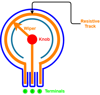
The center pin acts as a wiper moving across the resistive material. The voltage coming off the center pin (the wiper) increases the further it moves away from pin A, where power is applied. We measure the voltage of the center pin on the Arduino. Potentiometers are not polarized, so A&B are interchangeable.
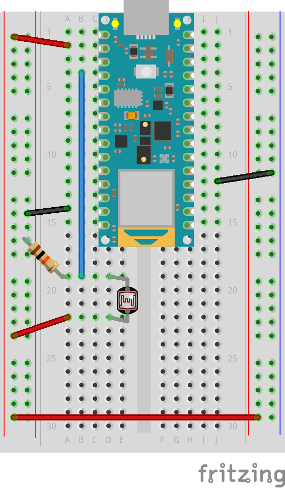
For other analog sensors (photocells, FSRs, flex sensors, etc.), you need to build a small circuit with a pulldown resistor, just like with the switches you worked with previously. In this case, you’re building your own voltage divider. A general rule of thumb for selecting the proper resistor value is to match the maximum sensor resistance. If you aren’t sure, start with a 10k resistor and see what your output is like.
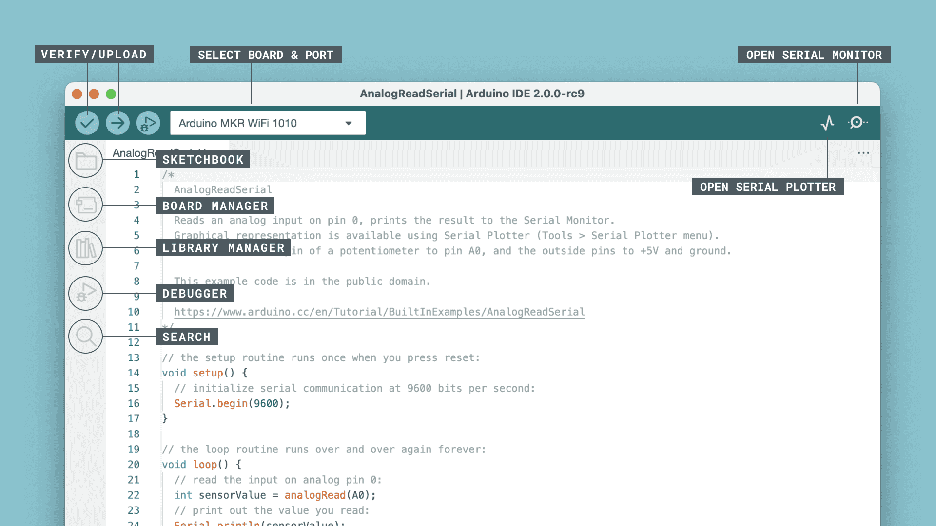
One more thing that will help you involves another new function called Serial.println() This sends information from the Arduino back to your computer. You can use the build in serial monitor to see this information. The serial monitor can be accessed through the Tools menu :
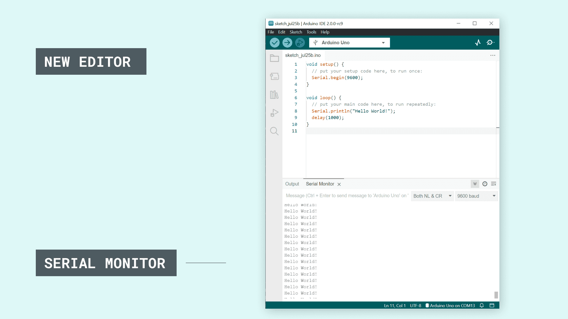
You can also access it by clicking on the magnifying glass icon on the right side of the main bar :
To start sending information serially, you must include Serial.begin() in your setup(). It takes an argument that indicates how fast it will communicate with your computer. For the time being, use 9600.
const int potPin=A0;// naming the input pin
int sensorVal;// holds the sensor value, also delays the blinking LED

void setup(){
    Serial.begin(9600);// open the serial connection at 9600 baud
}

void loop(){
    sensorVal=analogRead(potPin);// read the sensor value, save it in a variable
    Serial.println(sensorVal);// send the value of the sensor over the serial monitor
    delay(2);// slight pause for the cause
}
If you’re using a sensor that runs off of a voltage less than 3.3V, you will not get the full resolution of the sensor unless you call the analogReference() function and provide the Arduino with the appropriate reference voltage on the AREF pin.
So far, we’ve managed to get the microcontroller to read digital & analog inputs, and set a variety of fancy LED effects. Now it’s time to make some even more fancy things happen.
The microcontroller has the ability to read variable voltages, but what about sending out a variable voltage? Unfortunately, unless we’re using a high end microcontroller with a built in DAC (digital to analog converter), there’s no way to get a true analog voltage out of the microcontroller. However, we can fake it with a technique called Pulse Width Modification (PWM).
On your Arduino, you’ll notice that there are some digital pins with a ~ next to the number. These pins have PWM capabilities.
PWM is a method in which you pulse a pin on and off rapidly to give the illusion of a variable voltage. This is also called an effective voltage. The Arduino has an 8-bit PWM, which means there are 256 discrete steps available to us. In each period the pin will be pulled HIGH for a fraction of the time and LOW for the rest. The percentage of time this rapid on/off happens can be described as the duty cycle.
The method for communicating with the Arduino is called analogWrite(). It takes two arguments. The first argument is the pin you’re communicating with. The second argument is the value you wish to write. 0 is the same as 0V, 255 is the same a 3.3V. 127 would be 1.65V, and everything else in between maps out linearly.
It’s pretty simple to hook up a pot to an analog input and use that to control an LED’s brightness. Remember though, analogRead() returns a value between 0-1023, while analogWrite() only goes between 0-255. 256 goes into 1024 four times- we can divide the A0 reading by 4 to get a nice mapping between the two :
const int potPin=A0;// naming the input pin
const int ledPin=3;// led on PWM pin
int sensorVal;// holds the sensor value
int ledBright;// LED brightness

void setup(){
    pinMode(ledPin,OUTPUT);
}

void loop(){
    sensorVal=analogRead(potPin);// read the sensor value, save it in a variable
    ledBright=sensorVal/4;// divide by 4 to scale appropriately
    analogWrite(ledPin,ledBright);// PWM the LED
    delay(2);// pause for the cause
}
Speaking of mapping, it’s not a bad idea to think about how we would go about getting the full range of an LED when using a sensor like a photocell (which tends to have a more limited range than a pot).
Let’s assume we have a photocell that gives us 400 as a low value from analogRead() and 800 as an upper value. Clearly this isn’t going to work well for fading an LED. We could math our way out of the problem, but fortunately for us, we can use a function called map() which does the math for us. map() changes a number from one value to another based on a set of ranges. It takes 5 arguments : the initial value, the lowest value you would expect, the highest value you woudl epect, the lowest output you want, and the highest output youwant. So if we were to use map() in out existing example, and we wanted 400 from the sensor to be 0 to analogWrite(), and 800 from the sensor to 255 for analogWrite(), we could do the following :
sensorVal=analogRead(A0);
mappedVal=map(sensorVal,400,800,0,255);
analogWrite(mappedVal,ledPin);
map() doesn’t constrain numbers, so it’s possible to get mapped values outside the desired range. We can remedy that by 1) adding or subtracting some to the incoming values, or 2) calling the constrain() function. constrain() places an upper and lower bound on a number.
mappedVal=constrain(mappedVal,0,255);
Another way to deal with sensors that have variability in their inputs (and deal with environmental differences) is to calibrate your sensors, mapping from the max & min values.